


5
LC IO&M
B51031-004
Motor Services
Should the motor prove defective within a one-year period,
contact your local Loren Cook representative or your nearest
authorized electric motor service representative.
Changing Shaft Speed
All belt driven fans with motors up to and including 5HP are
equipped with variable pitch pulleys. To change the fan speed,
perform the following:
1. Loosen setscrew on driver (motor) pulley and remove key,
if equipped.
2. Turn the pulley rim to open or close the groove facing. If
the pulley has multiple grooves, all must be adjusted to
the same width.
3. After adjustment, inspect for proper belt tension.
Speed Reduction
Open the pulley in order that the belt rides deeper in the
groove (smaller pitch diameter).
Speed Increase
Close the pulley in order that the belt rides higher in the
groove (larger pitch diameter). Ensure that the RPM limits of
the fan and the horsepower limits of the motor are maintained.
Maximum RPM
HLC-B
Size
Maximum RPM
Standard
Reinforced
100
1740
-
120
1695
-
135
1780
-
150
1620
-
165
1335
-
180
1555
-
195
1345
-
210
1245
1345
225
1140
1185
245
1010
-
270
875
-
300
825
985
330
605
865
365
615
705
402
535
615
445
445
510
490
390
430
540
345
415
TLC-B
Size
Maximum RPM
Standard Reinforced
100
1755
-
120
1730
-
135
1750
-
150
1640
-
165
1325
-
180
1490
-
195
1325
-
210
1275
1325
225
1135
1180
245
1015
-
270
865
-
300
830
995
330
700
880
365
610
725
402
535
610
445
455
520
490
390
430
540
345
415
Pulley and Belt Replacement
1. Clean the motor and fan shafts.
2. Loosen the motor plate mounting bolts to relieve the belt
tension. Remove the belts.
3. Loosen the pulley setscrews and remove the pulleys from
the shaft.
•
If excessive force is required to remove the pulleys, a three-
jaw puller can be used. This tool, however, can easily warp
a pulley. If the puller is used, inspect the trueness of the pul-
ley after it is removed from the shaft. The pulley will need re-
placement if it is more than 0.020” out of true.
4. Clean the bores of the pulleys and place a light coat of oil
on the bores.
5. Remove grease, rust and burrs from the shaft.
6.
Place fan pulley on the fan shaft and the motor pulley on
the motor shaft. Damage to the pulleys can occur when
excessive force is used in placing the pulleys on their re
-
spective shafts.
7.
After the pulleys have been correctly placed back onto
their shafts, tighten the pulley setscrews.
8.
Install the belts on the pulleys. Align and adjust the belts
to the proper tension as described in
Belt and Pulley In
-
stallation
, page 2.
Bearing Replacement
The fan bearings are pillow block ball bearings.
1. Loosen screws on bearing cover.
2. Push bearing cover toward the wheel. As the bearing cov-
er moves toward the wheel, it will slide down to reveal the
bearings and shaft.
3. Remove the old bearing.
4. Remove any burrs from the shaft by sanding.
5. Slide new bearings onto the shaft to the desired location
and loosely mount bearings onto the bearing support.
Bearing bolts and setscrews should be loose enough to
allow shaft positioning.
6.
Correctly position the wheel and tighten the bearing bolts
securely to the bearing support.
7.
Align setscrews bearing to bearing and secure tightly to
the shaft.
NOTICE! Never tighten both pairs of setscrews before
securing bearing mounting bolts. This may damage
the shaft.
8.
Inspect the wheel position again. If necessary, re-adjust
by loosening the bearing bolts and setscrews and repeat
from step 5.
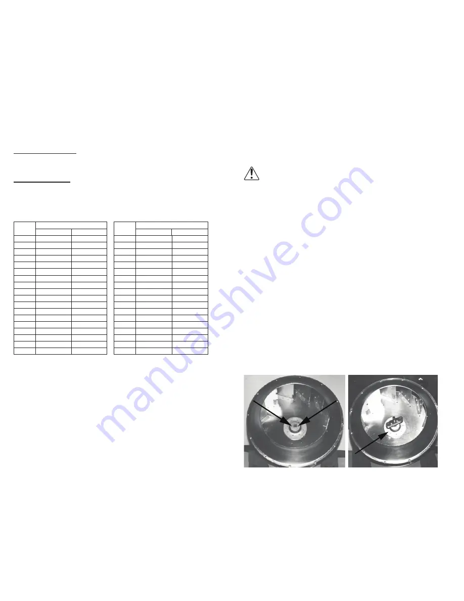
Wheel Replacement
1.
Drill two holes approximately centered between the shaft
and the edge of the hub OD with the following dimensions:
•
1/4” diameter
•
3/8” to 1/2” deep
•
180° apart in face of hub
2.
Tap 1/4” holes to 5/16” thread with the 5/16” hole tap. Do
not drill or tap any larger than recommended.
3. Screw the puller arms into the tapped holes full depth of
threads (3/8” to 1/2” approximately). Align center of pull
-
er with center of shaft. Make certain all setscrews in hub
(normally a quantity of two) are fully removed. Work puller
slowly to back wheel off the shaft.
Recommended Puller
Lisle No. 45000 Steering Wheel Puller. This puller is avail
-
able at most automotive parts retail outlets.
Wheel Puller
Drilled Hole Location
Wheel-to-Inlet Clearance
The correct wheel-to-inlet clearance is critical to proper fan
performance. This clearance should be verified before initial
start-up since rough handling during shipment could cause a
shift in fan components. Refer to wheel/inlet drawing below for
correct overlap.
Adjust the overlap by loosening the wheel hub and moving
the wheel along the shaft to obtain the correct value.