LBS DRAGON POWER PLUS 15 Скачать руководство пользователя страница 62

61

(2)

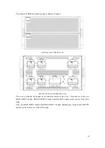
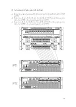
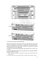
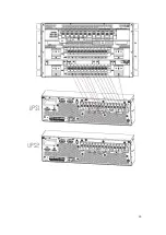
3-phase input and 3-phase output with dual input

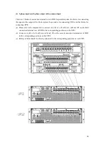
(a) Remove these copper sheets (named B1) between mA and bA, mB and bB, mC and bC of COP

and UPS.

(b) Connect oA, oB, oC, oN, mN, bN, mA, bA, mB, bB, mC, bC PE on the third connection

terminal row of POD to the corresponding positions on the UPS1.

(c) Connect oA, oB, oC, oN, mN, bN, mA, bA, mB, bB, mC, bC PE on the second connection

terminal row of POD to the corresponding positions on the UPS2.

Содержание DRAGON POWER PLUS 15

Страница 1: ...DRAGON POWER PLUS 15 15 KVA 60 KVA UPS USER MANUAL...

Страница 2: ...ge of technical support and service Customers can contact our local office or customer service center for help The manual will update irregularly due to the product upgrading or other reasons Unless o...

Страница 3: ...er who installs or operates the equipment should be well trained in electricity and safety and familiar with the operation debug and maintenance of the equipment Warning Label The warning label indica...

Страница 4: ...roper environment more detail in section 2 3 Debug Operate Make sure the grounding cable is well connected before connecting the power cables the grounding cable and neutral cable must be in accordanc...

Страница 5: ...utions should be followed implicitly at all times Particular attention should be paid to the recommendations concerning local environmental conditions and the provision of protective clothing first ai...

Страница 6: ...glasses rubber gloves and skirt when operating the battery Otherwise you may become blind if acid enters your eyes and your skin may be damaged by the acid At the end of battery life the battery may...

Страница 7: ...igurations are provided in Table 1 1 Table 1 1 UPS Configuration Item Components Quantity Remark 10 15kVA Circuit Breakers 4 Optional Dual Input 1 Standard Parallel Card 1 Optional Dry Contact Card 1...

Страница 8: ...rear views The UPS front views are shown as Figure 1 1 Rear panel As shown in Figure 1 2 the UPS rear panel offers the following components SNMP Optional Parallel Optional RS485 RS232 USB Optional Co...

Страница 9: ...2 1 UPS System Description The Rack UPS is configured by the following part Rectifier Charger Inverter Static bypass switch One or several battery strings should be installed to provide backup energy...

Страница 10: ...ies DC power to the inverter while simultaneously FLOAT or BOOST charging its associated backup battery The Normal mode structure is shown in Fig 1 4 Figure 1 4 Normal mode operation diagram 1 2 2 2 B...

Страница 11: ...ruption in power to the critical AC load Should the inverter be asynchronous with the bypass the static switch will perform a transfer of the load from the inverter to the bypass with power interrupti...

Страница 12: ...ation diagram Danger During Maintenance mode dangerous voltages are present on the terminal of input output and neutral even with all the modules and the LCD turned off 1 2 2 5 ECO Mode To improve sys...

Страница 13: ...inverter shuts down when the battery reaches the End of Discharge Voltage EOD The UPS may be programmed to System Auto Start Mode after EOD The system starts after a delay time when the AC mains recov...

Страница 14: ...raturefor batteriesis 20 25 Operatingabove 25 will reduce the battery life and operation below 20 will reduce the battery capacity The battery will generate a little amount of hydrogen and oxygen at t...

Страница 15: ...at least 0 5m of space on each side 3 Condensation to water drops may occur if the UPS is unpacked in a very low temperature environment In this case it is necessary to wait until the UPS is fully dr...

Страница 16: ...unterclockwise and then insert it 2 4 2 Rack Installation Battery cabinets must be installed firstly because battery cabinets are too heavy And two or more installation personnel are required to insta...

Страница 17: ...rom the middle of the batteries in series See Figure 2 4 Figure 2 4 Battery connection diagram Danger The battery terminal voltage is of more than 200Vdc please follow the safety instructions to avoid...

Страница 18: ...described below Ambienttemperature 30 AC loss less than 3 DC loss less than1 The length of the AC power cables are no longer than 50 m and the length of the DC power cables are no longer than 30 m Cur...

Страница 19: ...is open Attach necessary warning signs to these switches to prevent unauthorized operation 2 Open the back door of the cabinet remove the plastic cover The input and output terminal battery terminal a...

Страница 20: ...local and national codes When the cable holes does not goes through by cables it should be filled by the protective ring 2 7 Control and Communication Cables The rear panel of the cabinet provides dry...

Страница 21: ...losed function is settable Default Low battery alarming J8 2 BAT_LOW_ALARM_NO Output dry contact Normally open function is settable Default Low battery alarming J8 3 BAT_LOW_ALARM_GND Common terminal...

Страница 22: ...ture detection R25 5Kohm B25 50 3275 please confirm with the manufacturer or contact the local maintenance engineers when placing an order Remote EPO Input Port J4 is the input port for remote EPO It...

Страница 23: ...pen signal of BCB J6 2 2 GND_DRY Power ground for 24V J7 1 BCB_Online BCB on line input normally open BCB is on line when the signal is connecting with J7 2 J7 2 GND_DRY Power ground for 24V Battery W...

Страница 24: ...ure2 16 and description is shown in Table 2 11 Figure 2 16 Integrated warning dry contact interface diagram Table 2 11 General alarm dry contact interface description Port Name Function J9 1 GENERAL_A...

Страница 25: ...mmon input 3 phase in and 3 phase out dual input 3 phase in and 1 phase out common input 3 phase in and 1 phase out dual input 2 8 1 3 phase in and 3 phase out common input Use No 1 copper bar to conn...

Страница 26: ...terminal J4 EPO c Close the external input breaker the LCD screen of the ups will be lighted connect the MTR software and set the related parameters as below Change UsedKva to 10 or 6 from 15 or 10 T...

Страница 27: ...tion with the plastic rivet as shown in figure 2 18 Fig 2 17 Fix insulation film Fig 2 18 Graphic of insulation film fixed 4 Connect input phase A to No 6 copper bar then connect input phase B and pha...

Страница 28: ...d 1 phase out dual input 3 Fix the insulating film accessory to the No 5 copper bar as shown in Figure 2 20 and fixed in the corresponding position with the plastic rivet as shown in figure 2 21 Fig 2...

Страница 29: ...start operation key The front panel components of the UPS are described in table 3 1 Figure 3 1 Front panel of UPS Table 3 1 Description of front panel parts Item Name Description LCD Can operate cont...

Страница 30: ...ct capacity operational mode and the time of the system WarningInformation Display the warning information of the cabinet MainMenu Main menu includes Cabinet Data Setting Log Operate and System Users...

Страница 31: ...nd faults information and the data and time they occur and disappear Figure 3 4 Log Page The following Table 3 3 shows events of UPS History Log No LCD Display Explanation 1 Load On UPS Set Load On UP...

Страница 32: ...lear Incident above disappears 26 Bypass Overload Tout Set Bypass Over Load Timeout 27 Byp Overload Tout Clear Incident above disappears 28 Byp Freq Over Track Set Bypass Frequency Over Track Range 29...

Страница 33: ...otect Set Inverter Protect Inverter Voltage Abnormal or Power Back feed to DC Bus 68 Inverter Protect Clear Incident above disappears 69 Input Neutral Lost Set Input Grid Neutral Lost 70 Bypass Fan Fa...

Страница 34: ...ay Connect Fail Set Relay in open circuit 98 Relay Connect Fail Clear Incident above disappears 99 Relay Short Circuit Set Relay shorted 100 Relay Short Circuit Clear Incident above disappears 101 No...

Страница 35: ...touching the language icon COMM Device Address Setting the communication address RS232 Protocol Selection SNT Protocol Modbus Protocol YD T Protocol and Dwin For factoryuse Baud rate Setting the baud...

Страница 36: ...ystem auto start mode after EOD UPS start mode after battery end of discharging RATE Configure the rated Parameter For the factory use CONFIGURE Display mode Support Tower and Rack LCD display Back li...

Страница 37: ...arge days for running and hours of discharging TEST COMMAND Battery Test By touching the icon the system transfer to the Battery mode to test the condition of the battery Ensure the bypass is working...

Страница 38: ...ss input breaker and then the system starts initializing if not please one by one to turn on Input breaker Bypass input breaker and then the system starts initializing 2 The LCD in front of the cabine...

Страница 39: ...ter is running normally the UPS switches from the bypass to the inverter the bypass indicator bar is off and the load indicator bar flashes As shown in Figure 4 4 Figure 4 4 Normal mode 7 The startup...

Страница 40: ...steps of the start up are as follow 1 Confirm the batteries are correctly connected and then close the external battery circuit breakers 2 Press and hold the red button of battery cold start until th...

Страница 41: ...pleted from batteries 4 Close the external output power supply isolators to supply the loads and the system is working in battery mode 4 2 UPS Shut down If need to shut down UPS completely please firs...

Страница 42: ...pass mode Note Normally the system will transfer to the Normal mode automatically This function is used when the frequency of the bypass is over track and when the system needs to transfer to Normal m...

Страница 43: ...nal or from POD and the external battery breaker 2 After 30S the bypass indicator LED goes green and the load is powered through maintenance bypass breaker and static bypass 3 Turn off the maintenance...

Страница 44: ...rocess automatically 4 5 Installation of parallel operation system Normally 4 cabinets can be paralleled and the parallel function is optional if users need the function please confirm the configurati...

Страница 45: ...aintenance of the UPS please refer to Chapter 4 3 4 to transfer to maintenance bypass mode After maintenance re transfer to normal mode according to Chapter 4 3 5 5 3 Instruction for Maintaining Batte...

Страница 46: ...sulfuric acid and disposed of in accordance with local regulations The waste lead acid battery is a kind of hazardous waste and is one of the major contaminants controlled by government Therefore its...

Страница 47: ...40 2 Method of specifying the performance and test requirements of UPS IEC62040 3 Note The above mentioned product standards incorporate relevant compliance clauses with generic IEC and EN standards f...

Страница 48: ...it Parameter Rated capacity kVA 10 15 Grid System 3 Phases Neutral Ground Rated AC Input Voltage Vac 208 220 three phaseandsharing neutral with the bypass input Rated Frequency Vac 50 60Hz Input volta...

Страница 49: ...ttery Charge V cell 2 4V cell selectable from 2 3V cell 2 45V cell Constant current and constant voltage charge mode Battery Charging Power Max Current kW 10 UPS capacity selectable from 1 20 UPS capa...

Страница 50: ...utral cable A 1 7 In Rated frequency Hz 50 60 Switch time between bypass and inverter ms Synchronized transfer 0ms Bypass voltage range Settable default 20 15 Upper limit 10 15 20 25 Lower limit 10 15...

Страница 51: ...50 Interface Standard RS232 RS485 Dry Contact Option SNMP Parallel USB...

Страница 52: ...is for single UPS and the other is for 2 UPS in parallel 1 POD for single system The outlook of POD for single system is shown as Figure 1 A Front view with the cover B Front view without the cover T...

Страница 53: ...n terminal occurs MAIN INPUT mA mB mC mN BYPASS INPUT bA bB bC bN OUTPUT oA oB oC oN Ground PE Note For the factory default configuration mA and bA mB and bB mC and bC are short connected by the coppe...

Страница 54: ...he UPS user manual 1 3 phase input and 3 phase output with common input a Please refer tothe diagram below connect oA oB oC oN mN mA mB mC PE on the bottom connection terminal row of POD to the corres...

Страница 55: ...nection these copper sheets are optional they are named 3 1 kit for UPS and 3 1 kit for single POD 3 1 kit for UPS contains 4 blocks of copper sheets they are named UPS 4 UPS 5 UPS 6 UPS 7 3 1 kit for...

Страница 56: ...corresponding positions on the UPS 4 3 phase input and 1 phase output with dual input NOTE The UPS and COPare both configured as the type of 3 phase input and 3 phase output as default If configuring...

Страница 57: ...et UPS 7 g Short bA bB and bC on the UPS connection terminal row with the copper sheet UPS 5 h Connect oA and oB on the bottom connection terminal row of POD to the copper sheet UPS 4 with cables i Co...

Страница 58: ...e cover The cover is attracted by magnet on the both side Remove the cover 7 breakers occur they are MAIN INPUT breaker BYPASS INPUT breaker and OUTPUT breaker on the top row from left to right They a...

Страница 59: ...ver Remove the protective cover the connection terminal occurs MAIN INPUT mA mB mC mN BYPASS INPUT bA bB bC bN OUTPUT oA oB oC oN Ground PE Note For the factory default configuration mA and bA mB and...

Страница 60: ...re are 4 kinds of cable connections NOTE Before connecting the cables please first confirm the configuration of the UPS generally the UPSis configured as the type of 3 phase input and 3 phase output 3...

Страница 61: ...necting UPS2 and the third is for connecting UPS1 a Please refer to the diagram below connect oA oB oC oN mN mA mB mC PE on the third connection terminal row of POD to the corresponding positions on t...

Страница 62: ...mB and bB mC and bC of COP and UPS b Connect oA oB oC oN mN bN mA bA mB bB mC bC PE on the third connection terminal row of POD to the corresponding positions on the UPS1 c Connect oA oB oC oN mN bN...

Страница 63: ...heet POD B3 c Short oC oN mN and bN on the top connection terminal row of POD with the copper sheet POD B4 d Short mA bA bB and bC on the top connection terminal row of POD with the copper sheet POD B...

Страница 64: ...these copper sheets are optional they are named 3 1 kit for UPS and 3 1 kit for single POD 3 1 kit for UPS contains 4 blocks of copper sheets they are named UPS 4 UPS 5 UPS 6 UPS 7 3 1 kit for parall...

Страница 65: ...Short bA bB and bC on the UPS connection terminal row with the copper sheet UPS 5 h Connect oA and oB on the bottom connection terminal row of POD to the copper sheet UPS 4 with cables i Connect oC o...

Страница 66: ...65...

Страница 67: ...www lbspower com Espa ol English...

Отзывы: