5
A STEELFORT PRODUCT
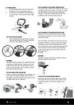
ATTACH THE BLADE GUARD
•
Attach the guard using the hex key included.
The guard is attached to the lower shaft with
two hex screws facing the operator.
WARNING
Use only original manufacturer’s replacement parts,
accessories and attachments. Failure to do so can
cause poor performance, possible injury and may
void your warranty. Never use the trimmer without
the guard securely attached!
ATTACH/DETACH CUTTING HEADS
Remove the brush cutting blade nut and flange. Line
up the holes of flange and shield, use the hex key
included to prevent the shaft from turning. Turn the
included socket wrench clockwise.
8
SPECIFICATIONS
All speci
fi
.
g
n
i
t
n
ir
p
f
o
e
m
i
t
e
h
t
t
a
e
l
b
a
li
a
v
a
n
o
i
t
a
m
r
o
f
n
i
t
c
u
d
o
r
p
t
s
e
t
a
l
e
h
t
n
o
d
e
s
a
b
e
r
a
s
n
o
i
t
a
c
We reserve the right to make changes at any time without notice.
ASSEMBLY
When assembling this machine, please follow the instructions for assembly steps.
1. Connecting the upper and lower shafts:
Remove the rubber shaft plug and cap. Pull up the spring-loaded pin
(1) and push the lower shaft (2) into the aluminum coupler until the
spring loaded pin (1) clicks into the hole (3) of the aluminum coupler.
Once the spring-loaded pin is completely inserted, tighten the coupler
knob (4).
2. Assemble the handle :
3. Attaching the blade guard:
Attach the guard using the hex key included. The guard is attached to the lower shaft with two hex
screws facing the operator.
Warning!
Use only original manufacturer’s replacement parts, accessories and attachments. Failure
to do so can cause poor performance, possible injury and may void your warranty.
Never use the
trimmer without the guard securely attached!
Model name . . . . . . . . . . . . . . . . . .BCI26
Engine type. . . . . . . . . . Air-Cooled, 2-Cycle
Engine displacement . . . . . .. . . . .. . . 25.4cc
Rated motor power . . . . . . . . . . . . . . 0.7kw
Lubrication . . . . . . . . . . . . Fuel/Oil Mixture
Fuel/Oil ratio. . . . . . . . . . . . . . . . . . . 25:1
Volumes of fuel tank . . . . . . . . 20 oz. (600ml)
Trimmer mechanism . . . . . . . . . Bump Head
Cutting path diameter . . . . . . . .17in (430mm)
Trimming line. . . . . . . . . . . 0.095 in. (2.4mm)
Max. engine speed (with cutting
attachment, no-load) . . . . . . . . . . 11500/min
Put left handle rubber cover(3) on the shaft between
the two arrow positioning label, fix the upper handle (2)
with lower handle (4) to the tube with screws (1) and nuts
(5) tightly enough.
ATTACH/DETACH THE BRUSH CUTTING BLADE.
Remove the nut and outer flange. Place the blade,
outer flange, shield and nut on the trimmer head in
the order as shown.
Note the blade rotation direction must match arrows
marked on the blade. Line up the holes of the flange
and shield, use the hex key included to prevent the
shaft from turning. Turn counter-clockwise, ensuring
the nut is tight. To detach the brush cutting blade
turn the nut clockwise until it is released from the
shaft and remove
the blade.
WARNING
Verify the cutting head is tight and has been assem-
bled correctly before every use!
FIT/ATTACH THE SHOULDER HARNESS
Place strap over the operators head and one shoul-
der. Adjust the harness length to the operators arm
reach. Clip harness to the harness hanger on the
trimmer.
4. Attach/detach cutting heads:
a) Remove the brush cutting blade nut and flange. Line up the holes of flange and shield, use the
hex key included to prevent the shaft from turning. Turn the included socket wrench clockwise.
b) Attach/detach the string trimmer head. Line up the holes of flange and shield, use the hex key
included to prevent the shaft from turning. To attach the string trimmer head turn counter-clockwise
until snug. To detach the string trimmer head turn clockwise until it is released from the shaft.
c) Attach/detach the brush cutting blade. Remove the nut and outer flange. Place the blade, outer
flange, shield and nut on the trimmer head in the order as shown. Note the blade rotation direction
must match arrows marked on the blade. Line up the holes of the flange and shield, use the hex key
included to prevent the shaft from turning. Turn counter-clockwise, ensuring the nut is tight. To
detach the brush cutting blade turn the nut clockwise until it is released from the shaft and remove
the blade.
WARNING: Verify the cutting head is tight and has been assembled correctly before every use!
5. Fit/attach the shoulder harness:
Place strap over the operators head and one shoulder. Adjust the harness length to the operators
arm reach. Clip harness to the harness hanger on the trimmer.
9
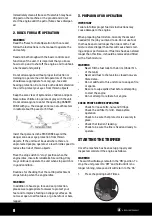
ATTACH/DETACH THE STRING TRIMMER HEAD
Line up the holes of flange and shield, use the hex key
included to prevent the shaft from turning. To attach
the string trimmer head turn counter-clockwise
until snug. To detach the string trimmer head turn
clockwise until it is released from the shaft.
ATTACH HANDLE
1.
Put left handle rubber cover (3) on the shaft
between the two arrow positioning label.
2.
Fix the upper handle (2) with lower handle (4)
to the tube with screws (1) and nuts (5) tightly
enough.


