


Launch
X-631 Wheel Aligner Maintenance Manual
Testing for Cabinet Assembly
2-11
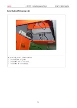
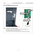
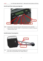
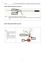
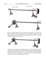
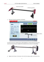
Item12: Antenna and RF Cable Inspection
Note:
Check if RF cable and cupula antenna are damaged, and check if the connectors and antenna plastic bush are
fastened firmly.
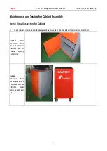
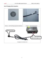
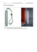
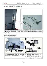
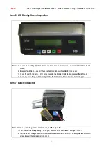
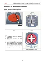
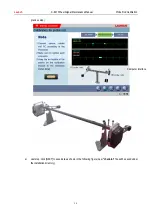
Item13: Printer Inspection
1.
Check and clear away the oil dirt and dust inside the printer;
2.
Check if the nozzle is blocked by self-testing of the printer.
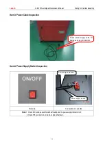
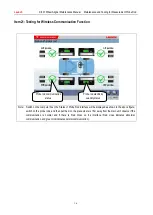
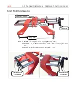
1.
Check if power cable and USB connecting cable
are damaged;
2.
Check if the power supply box is distorted, and the
contacts are in good condition.
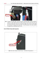
Color cartridge
Black-white cartridge
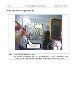
Printer power supply
USB connecting cable
Printer power supply
connecting cable


