Drawings
44
Elektronik-Systeme Lauer, MAEN971
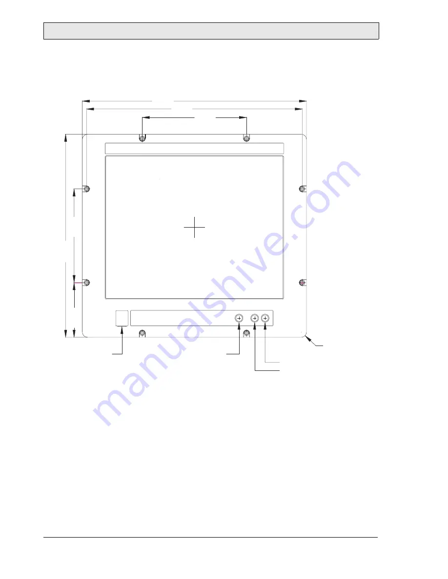
7.4 EPC PM 1700t/1700 Nautic Front
View
200±0.1
430±0.1
414±0.1
390±0.1
105±0.1
1 x USB waterproof
180±0.1
Brightness Down
Brightness Up
Power On-Off
R10.0
Страница 1: ...EPC PM Nautic Installation Manual MAEN971 2009 01 English...
Страница 2: ...ion manual prior to installing and using this equipment Only qualified personnel may install operate or repair this equipment Elektronik Systeme Lauer GmbH Co KG is not responsible for modified altere...
Страница 3: ...f Parts 10 3 1 EPC PM Nautic 10 3 2 Display 11 3 3 Communication Ports 230 V AC 12 3 4 Communication Ports 24 V DC 12 3 5 Configuration of COM4 13 3 6 Motherboard 14 3 7 Assembly 14 3 8 Power Supply 1...
Страница 4: ...1500t 1500 Nautic Cut Out Drawing 42 7 3 EPC PM 1500t 1500 Nautic Outline Drawings 43 7 4 EPC PM 1700t 1700 Nautic Front View 44 7 5 EPC PM 1700t 1700 Nautic Cut Out Drawing 45 7 6 EPC PM 1700t 1700 N...
Страница 5: ...DNV ABS RS CCS KR EN 60945 EPC PM 1500t 1500 Nautic X X X X X X EPC PM 1700t 1700 Nautic X X X X X X X X X X EPC PM 1900t 1900 Nautic X X X X X X X X X X EPC PM 2100t 2100 Nautic X X X X X X X X X X...
Страница 6: ...he EPC This may cause fire or electrical shock Only qualified personnel may operate the EPC Storing the EPC where the temperature is lower higher than recommended in this manual can cause the LCD disp...
Страница 7: ...ding to the accompanying installation instructions Only qualified personnel may install the EPC Separate the high voltage signal and supply cables Make sure that the voltage and polarity of the power...
Страница 8: ...trical supply Clean the display and surrounding front cover with a soft cloth and mild de tergent Replacing the battery incorrectly may result in explosion Only use batteries recommended by the suppli...
Страница 9: ...wer cable Standard power cable European or US standard for units with 230 V AC power supply Length approximately 3 0 m 24 V DC units are delivered without cable Installation manual This manual describ...
Страница 10: ...10 Elektronik Systeme Lauer MAEN971 3 Description of Parts 3 1 EPC PM Nautic The EPC PM Nautic consists of a Front Unit and a PC Unit These are installed in the same way independent of the display siz...
Страница 11: ...he monitor off Press the power button again Turns the monitor on Press brightness down on the dimmer button Makes the display darker Press brightness up on the dimmer button Makes the display brighter...
Страница 12: ...USB 1 USB 2 0 LAN 2 RJ 45 USB 4 USB 2 0 USB 3 USB 2 0 and fuse terminal LPT 1 DB25F PCI slot 1 PCI slot 2 mini jack Power remote screw terminal Power screw Power remote PS 2 Mouse Keyboard COM1 DB9M C...
Страница 13: ...as RS485 or AUX using jumpers When configured as RS485 the pins are assigned at half duplex according to be low Jumper positions Description 1 3 2 4 7 9 8 10 On RS232 default setting 3 5 4 6 7 9 8 10...
Страница 14: ...n the supplied mounting kit Note The quality of the memory module may influence the system stability When updating the memory module or adding a second one please only use memory modules cleared by El...
Страница 15: ...s carried out via a double pole connector Phoe nix MST BT 2 5 2 The EPC PM Nautic is certified for the connection to protective grounded power supply according to EN60950 The controlling transformer h...
Страница 16: ...one in accordance with ATX specification via the ATX power switch the red button next to the power supply Should a correct automatic booting not function then this can have the follow ing reason In th...
Страница 17: ...lingual C and D NTFS The operating system and other programs installed on drive C while drive D is a complete free partition which for example can be used for your data beneficial for example for data...
Страница 18: ...OS Features Time Current time Standard CMOS Features Check that all IDE Devices HD CD and CF are cor rectly recognized Advanced BIOS Features First Boot Device HDD 1 Advanced BIOS Features Second Boot...
Страница 19: ...formation and therefore no improvement is achieved from a higher setting Install the touch screen drivers in accordance with the instructions Note Higher settings can even seriously damage the graphic...
Страница 20: ...h Screen Installation Technical data check the BIOS settings when re installing Serial Tsharc 12 Touch Controller Com 3 check the BIOS settings 3E8 hex IRQ 4 9600 bps Perform the SETUP EXE under E Dri...
Страница 21: ...Operation Elektronik Systeme Lauer MAEN971 21 1 Follow the instructions on the screen and press Continue 2 Accept the license provisions...
Страница 22: ...Operation 22 Elektronik Systeme Lauer MAEN971 3 Select Autodetect or manually select the technical connection data...
Страница 23: ...23 4 Press Finish and follow the instructions for a re start 5 After a re start of the operating system you will find Hampshire Control Panel among the programs 6 Calibrate the touch screen with your...
Страница 24: ...atic driver search of the graphic board driver The graphic driver is located on the delivered Driver CD or on partition E EPC PM Grafic 1 Run Setup exe from the Utilities directory 2 After finishing t...
Страница 25: ...second network card open the EXE file from the drive directo ry Drive E Driver EPC PM LAN Confirm each installation step and re start the EPC PM Nautic at the end of the installation After the re sta...
Страница 26: ...Operation 26 Elektronik Systeme Lauer MAEN971...
Страница 27: ...arried out by au thorized personnel Only the expansion of hardware with memory and plug in cards is permissible within the defects liability period Attention Deadly Peril Make sure that your electrost...
Страница 28: ...Changing the Fan 1 To change the fan you have to remove the left hand part of the rear enclo sure To open the enclosure remove the six 6 marked screws with an Allen key 2 Lift the enclosure and pull o...
Страница 29: ...he cable prior to pulling the cable out so that the new fan can be plugged in correctly Unplug and remove the fan 4 Remove the protective cover of the fan and remove the fan with a Phillips head screw...
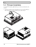
Страница 30: ...PCI board Installation To install a PCI board the right hand side part of the rear enclosure has to be removed 1 To open the enclosure remove the marked seven screws with an Allen key After removing...
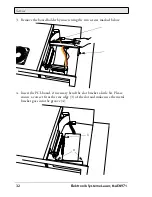
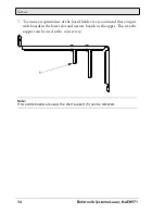
Страница 31: ...me Lauer MAEN971 31 The picture of the opened appliance below shows the board holder 1 and the 2 PCI slots 2 2 Remove the cover of the desired slot to insert your PCI board by removing the screw and p...
Страница 32: ...ve the board holder by unscrewing the two screws marked below 4 Insert the PCI board if necessary bend the slot bracket a little bit Please ensure a correct fit at the rear edge 3 of the slot and make...
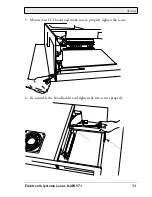
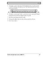
Страница 33: ...Service Elektronik Systeme Lauer MAEN971 33 5 Mount your PCI board and make sure to properly tighten the screw 6 Re assemble the board holder and tighten the two screws properly...
Страница 34: ...nsure an optimal use of the board holder we recommend that you put wide boards in the lower slot and narrow boards in the upper This way the support can be used in the correct way Note If two wide boa...
Страница 35: ...Module 1 To change or expand the memory card you have to remove the left hand part of the rear enclosure To open the enclosure remove the six 6 marked screws with an Allen key 2 Lift the enclosure and...
Страница 36: ...ew of the slots Pull out the ribbon cable 1 and move it to the top according to arrow 2 4 The picture above shows one free 3 and one occupied slot If a memory expansion is carried out the memory modul...
Страница 37: ...ng to the below picture The memory board is now loose and can be removed 6 To mount a new memory board center it into the slot and push it firmly but gently down until the holding brackets snap shut 7...
Страница 38: ...Service 38 Elektronik Systeme Lauer MAEN971...
Страница 39: ...al IP65 Rear panel seal IP20 according to DIN EN 60529 Weight 8 5 kg 10 7 kg 13 kg 18 5 kg Processor Intel Celeron M 1 3 GHz Cache PCI Clock 512 KB level 2 cache 400 MHz Bus System chipset Intel 82855...
Страница 40: ...ber of colors 16 7 million View angle up down left right typical 50 60 75 75 89 Light intensity typical 250 cd m2 300 cd m2 Contrast ratio 450 1 1500 1 1000 1 Response time 6 ms 19 ms 15 ms 10 ms 13 m...
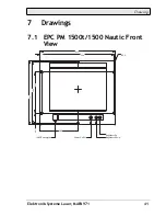
Страница 41: ...Drawings Elektronik Systeme Lauer MAEN971 41 7 Drawings 7 1 EPC PM 1500t 1500 Nautic Front View R5 0 394 412 Brightness Up Brightness Down 351 222 333 206 1x USB waterproof 64 5 Power On Off...
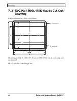
Страница 42: ...PM 1500t 1500 Nautic Cut Out Drawing Cut out dimensions 369 0 x 324 0 mm Mounting method 6 x M6x25 V2A screws DIN 6912 Screws and o ring seals are included Max 5 mm thick mounting frame 369 197 394 32...
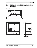
Страница 43: ...Drawings Elektronik Systeme Lauer MAEN971 43 7 3 EPC PM 1500t 1500 Nautic Outline Drawings Bottom view Rear view Side view 395 367 12 169 85 28 R3 0 Fan 188 5 363 336 5 104 5 87 5 144 2 0 0 0 134 41...
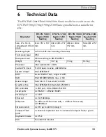
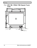
Страница 44: ...Drawings 44 Elektronik Systeme Lauer MAEN971 7 4 EPC PM 1700t 1700 Nautic Front View 200 0 1 430 0 1 414 0 1 390 0 1 105 0 1 1 x USB waterproof 180 0 1 Brightness Down Brightness Up Power On Off R10 0...
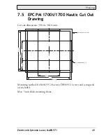
Страница 45: ...Nautic Cut Out Drawing Cut out dimensions 396 0 x 364 0 mm Mounting method 8 x M6x25 V2A screws DIN 6912 Screws and o ring seals are included Max 5 mm thick mounting frame 200 0 2 396 1 0 414 0 2 374...
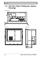
Страница 46: ...Drawings 46 Elektronik Systeme Lauer MAEN971 7 6 EPC PM 1700t 1700 Nautic Outline Drawings Bottom view Rear view Side view 395 367 12 169 85 28 R3 0 Fan 188 5 363 336 5 104 5 87 5 144 2 0 0 0 134 41...
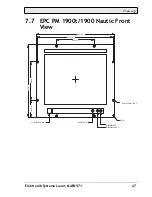
Страница 47: ...ktronik Systeme Lauer MAEN971 47 7 7 EPC PM 1900t 1900 Nautic Front View 230 0 1 Power On Off 483 2 0 1 465 2 0 1 235 0 1 1 x USB waterproof 104 5 0 1 444 0 1 8 x boreholes 6 5 R10 0 Brightness Down B...
Страница 48: ...Nautic Cut Out Drawing Cut out dimensions 438 x 416 mm Mounting method 8 x M6x25 V2A screws DIN 6912 Screws and o ring seals are included Max 5 mm thick mounting frame 426 0 2 230 0 2 465 2 0 2 438 1...
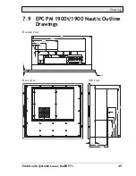
Страница 49: ...gs Elektronik Systeme Lauer MAEN971 49 7 9 EPC PM 1900t 1900 Nautic Outline Drawings Bottom view Rear view Side view R3 0 434 386 5 188 6 104 6 47 5 12 10 412 388 2 238 7 154 7 136 7 144 2 0 0 0 134 4...
Страница 50: ...0 Elektronik Systeme Lauer MAEN971 7 10 EPC PM 2100t 2100 Nautic Front View 223 0 1 Power On Off 534 0 1 516 0 1 313 0 1 1 x USB waterproof 105 0 1 Brightness Down Brightness Up 8 x boreholes 6 5 R10...
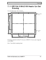
Страница 51: ...t 2100 Nautic Cut Out Drawing Cut out dimensions 500 x 443 mm Mounting method 8 x M6x25 V2A screws DIN 6912 Screws and o ring seals are included Max 5 mm thick mounting frame max thickness 5 0 mm 313...
Страница 52: ...Drawings 52 Elektronik Systeme Lauer MAEN971 7 12 EPC PM 2100t 2100 Nautic Outline Drawings Bottom view Rear view Side view 498 418 5 79 5 R3 0 441 2 415 5 164 2 134 40 144 Fan...
Страница 53: ...Tel 46 40 35 86 00 Fax 46 40 93 23 01 www beijerelectronics com info beijerelectronics com SUBSIDIARY CENTRAL EUROPE Elektronik Systeme Lauer GmbH Co KG Kelterstra e 59 72669 Unterensingen Germany Tel...