


Description of Parts
16
Elektronik-Systeme Lauer, MAEN971
3.9 Earthing System
The following items have to be observed to guarantee a safe dissipation of elec-
tronic interference:
– Appliance and switch board have to be connected to the nearest possible cen-
tral earthing point.
– Make sure of a possibly low inductive connection between appliance and
switch board.
– All data cables connected to the appliance have to be of the shield type.
– The screens have to be earthed on both sides. A low ohm connection between
the connected systems is essential. Avoid high equalizing currents through the
cable screen due to voltage fluctuations.
– The earthing connection is to be carried out with min. 4 mm² cross section.
3.10 ATX Power Switch
Power packs, main boards and operation systems are used in the EPC PM Nau-
tic , using up to date PC-technologies such as ATX and ACPI. Switching on the
appliances is done in accordance with ATX specification via the ATX power
switch (the red button next to the power supply).
Should a correct automatic booting not function then this can have the follow-
ing reason:
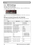
In the BIOS settings, the option
PWRON After PWR-Fail
in the
Integrated
Peripherals/Super IO Device
menu must be enabled, i.e.
On
. See also section
4.2 BIOS Settings
.
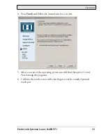
The operating system must be ended correctly using the
Shut down
command
from the operating system menu (Windows start menu), so that the operating
system of the EPC is shut down. The EPC must not be switched off while with
the operating system is still running.
The power pack now has to be separated from the power supply for a minimum
of 15 seconds prior to a re-start. During the booting process the main voltage
may not fall (not even for a short time) below the permitted value.
A manual actuation of the ATX power switch, i.e. to start the BIOS menu au-
tomatically to check and confirm correct settings, can be necessary if the system
registers an error during shut-down or booting. This is not a malfunction but a
safety feature.