background image

Intercom Installation Guide

26

Version 1.0

27

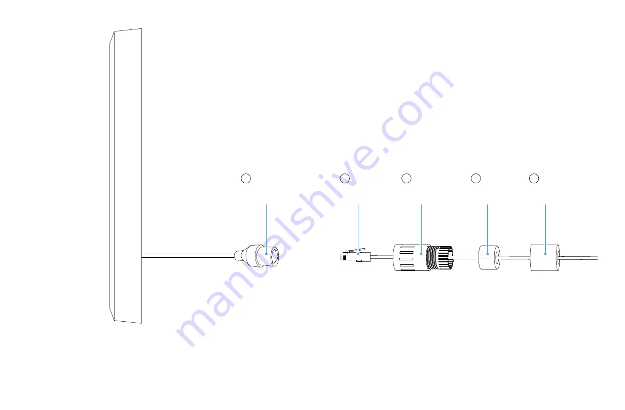
You may use an Ethernet cable to provide both power and 

internet to the device. Or you may utilize the direct power wires 

alongside onboard Wi-Fi or cellular.

4a.

Female RJ45

A

Male RJ45

Connector Seal

Split Gland

Cable Seal

Step 1: 

Feed B through C and E

Step 2: 

Plug B into A

Step 3:

 Connect A to C by twisting. Add D behind C

Step 4:

 Screw E into C

B

C

D

E

Содержание INT1LFCNA1

Страница 1: ...Installation Guide Intercom ...

Страница 2: ...ings you should know Included in the box Product details Installation Specifications Handling information Requirements for compliance 34 19 07 33 16 05 04 Model INT1LFCNA1 Document number 770 00012 V1 Revised on 08 03 2020 ...

Страница 3: ...res the iOS Manager App running on an iPhone 5S or newer Mounting Hardware Pan head screws Anchors Gel filled crimps Cable sealing components RJ45 male connector Product Latch Intercom Mounting plate Included in the Box Mounting Tools 2 Phillips head screwdriver TR20 Torx security screwdriver 1 5 drill bit for cable routing hole Requirements for Device 64 bit iOS device Latest version of the Latch...

Страница 4: ...Intercom Installation Guide 6 Version 1 0 7 Product Details Details and recommendations for power wiring and product specifications ...

Страница 5: ...t Details 12VDC 24VDC 50 Watts Supply Class 2 Isolated UL Listed DC Power Supply Choice of Ethernet Wi Fi and or LTE connection is required Minimum wiring recommendations Distance Power 12V 25ft 50ft 100ft 200ft 22 AWG 24 AWG 24V 18 AWG 22 AWG 16 AWG 18 AWG 16 AWG ...

Страница 6: ...PoE 802 3bt 50 Watts Supply Choice of additional Wi Fi and or LTE connection is optional Minimum wiring recommendations PoE Source 50W Shield Shielded Distance 328ft 100m CAT Type 5e 6 7 6a 8 AWG 10 24 AWG Ethernet cable recommended to meet CMP or CMR rating ...

Страница 7: ...Intercom Installation Guide 12 Version 1 0 13 Detail View of Cable RJ45 Female Type Connector Direct Power Connection ...

Страница 8: ...on 1 0 15 Product Details Note Refer to ADA Guidelines on mounting height Mounting Plate Centerline Mark Procedural Numbers Centerline Mark Support Cable Hook Microphone Display Navigational Buttons Security Screw Speaker Mesh Microphone ...

Страница 9: ...eduction Specifications For UL 294 installations the power source must be compliant to one of the following standards UL 294 UL 603 UL 864 or UL 1481 When powered via PoE the PoE source must be either UL 294B or UL 294 Ed 7 compliant For ULC 60839 11 1 installation the power source must be compliant to one of the following standards ULC S304 or ULC S318 Display Brightness 1000 nits Viewing angle 1...

Страница 10: ...Intercom Installation Guide 18 Version 1 0 19 Installation Follow these steps to proceed with installation ...

Страница 11: ...rcom Installation Guide 20 Version 1 0 21 Align the center mark on the mounting plate and center on wall Level and mark holes 1 and 2 Drill anchor and screw in place 1 Note Hole 2 is slotted for adjustments ...

Страница 12: ...22 Version 1 0 23 Find the center of the 1 5 inch cable bore hole using marks as a guide Temporarily remove the mounting plate and drill a 1 5 inch hole 2 Drill and set anchors for remaining holes 3 6 Reinstall the mounting plate ...

Страница 13: ...on 1 0 25 Important Keep the protective bumpers on Using the support cable hook the Intercom to the mounting plate for easier wiring 3 Align pocket in the bumper with the lower mounting plate tab Place the loop of support cable over hook ...

Страница 14: ...and internet to the device Or you may utilize the direct power wires alongside onboard Wi Fi or cellular 4a Female RJ45 A Male RJ45 Connector Seal Split Gland Cable Seal Step 1 Feed B through C and E Step 2 Plug B into A Step 3 Connect A to C by twisting Add D behind C Step 4 Screw E into C B C D E ...

Страница 15: ...ortant Ensure cables are dry and free of moisture before connecting 4b 5 Unhook the support cable remove bumpers and feed all wires and cables through the wall Use the center alignment pins to locate the product Place the Latch Intercom flush with the mounting plate and slide down until all mounting tabs fit snugly ...

Страница 16: ...Installation Guide 30 Version 1 0 31 Note We recommend forming a drip loop of cables to help avoid moisture condensation on connections or device Correct Incorrect Lock into place with the TR20 security screw 6 ...

Страница 17: ...ough the device is water resistant do not apply water or liquid directly to the screen Dampen a clean soft microfiber cloth with water and then wipe the screen gently Cleaning the speaker mesh To clean out debris from the speaker mesh perforations use a can of compressed air held 3 from the surface For particles that are not removed by compressed air painters tape can be used on the surface to pul...

Страница 18: ...ion in the band 5150 5250 MHz is only for indoor use to reduce the Reorient or relocate the receiving antenna Increase the separation between the equipment and receiver Connect the equipment into an outlet on a circuit different from that to which the receiver is connected Consult the dealer or an experienced radio TV technician for help Regulatory Compliance potential for harmful interference to ...

Страница 19: ...e if using PoE is 802 3bt 50W Further troubleshooting information is available on the support website at support latch com The Latch Manager app is necessary to configure the Latch Intercom Further configuration information can be found on the support website at support latch com Latch Intercom has been tested for UL294 compliance employing firmware version INT1 3 9 The current firmware version ca...

Страница 20: ...Intercom Installation Guide 38 Version 1 0 39 ...

Страница 21: ......

Отзывы: