ICS-6-OEM Instruction Manual
01807-53-000
Issue 5 19 January 2021
LASERMET
ICS-6-OEM
INSTRUCTION MANUAL
FAIL SAFE LASER
INTERLOCK CONTROLLER
Страница 1: ...ICS 6 OEM Instruction Manual 01807 53 000 Issue 5 19 January 2021 LASERMET ICS 6 OEM INSTRUCTION MANUAL FAIL SAFE LASER INTERLOCK CONTROLLER ...
Страница 2: ...0 6 2 ICS 6 OEM Illuminated Sign Control Output 13 6 3 Interlock Operator Output Contacts 15 7 Expansion Boards 21 7 1 Installing Expansion Boards 21 8 Mismatch Detector 22 8 1 Configurable Options for Safety Circuit Mismatch Events 22 8 2 Clearing a Mismatch Fault Indication 24 8 3 Mismatch Detector Remote Test and Reset 25 9 LED Indicators 26 10 Operation 28 10 1 Starting Up 28 10 2 Resuming Ope...
Страница 3: ...Lasermet certifies that this product complies with the basic requirements for health and safety as provided by the following directives and standards Directives Machinery Directive 2006 42 EC Low Voltage Directive 2014 35 EU EMC Directive 2014 30 EU Standards EN ISO 13849 1 2015 Safety of Machinery Safety related parts of Control Systems EN 60947 1 2007 A1 2010 A2 2014 Low Voltage Switchgear and C...
Страница 4: ...t fixing holes They must not come into contact with each other or any other moving part when in use The parts should never be subject to impact or mechanical strain Safety switches should never be defeated or bypassed It is imperative that all steps are taken to ensure that any spare actuators are made unavailable such that they cannot be used to defeat the switch or reduce the protection offered ...
Страница 5: ...tem compliant with EN ISO 13849 1 up to performance level e Seven safety interlock outputs each rated at 4A resistive 50VDC are provided to enable the laser operate door locks provide signals to a PLC etc The interlock outputs are volt free contacts which close when the system is armed Each contact actually comprises two contacts in series In the event of one contact failing to open when the contr...
Страница 6: ... filter windows Glaser Jailer Safety Logic Plus Network Interface Lasermet provides a full range of laser interlock equipment including control systems interlock switches illuminated warning signs laser shutters door locks external power supplies etc which can be connected to provide a complete laser interlock system Full support design and installation is available from Lasermet please contact us...
Страница 7: ...vel e the system must be wired as described in this manual using suitably rated door sensors and measures taken to minimise the effects of common cause failures in the sensors and wiring which may be connected to the unit Achieved Characteristics Architecture Category 4 Performance Level PL PL e PFH 1 h 2 47 x 10 8 MTTFd 381 years Mission Time 20 years Diagnostic Coverage DC 99 HIGH ...
Страница 8: ... contacts 5 1 Positioning The ICS 6 OEM should be mounted in a convenient position for wiring It should be inaccessible by operators It has indicator lights on its top surface which would normally only need to be observed by installation and maintenance personnel During installation wired connections will need to be made from the ICS 6 OEM to all the interlocked doors warning signs laser interlock...
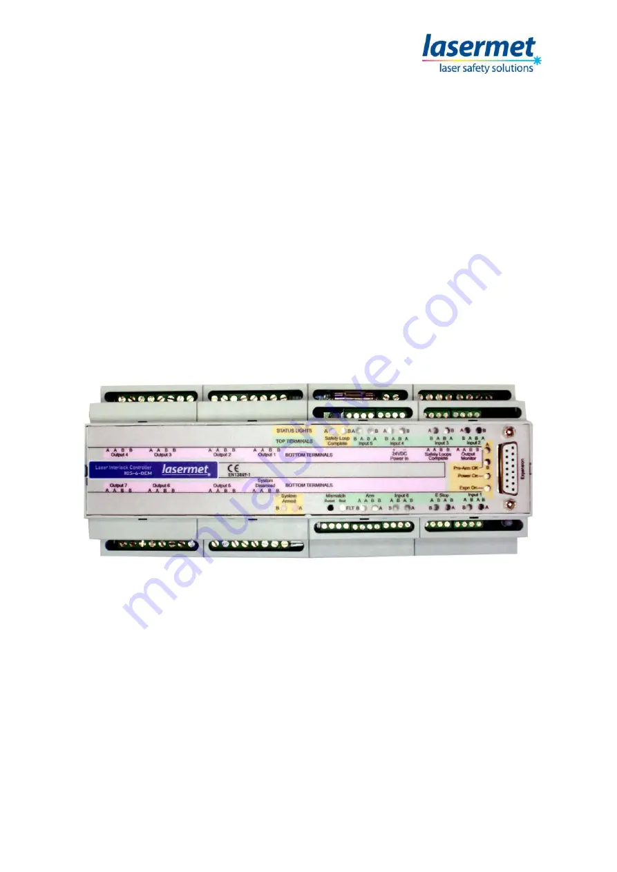
Страница 9: ... position of the interlock and arm input signals and the state of the controller Next to these on a green background are the identifications for the top rows of terminals The Top terminals refer to the terminals at the front of the unit Nearest the centre of the label on a pink background are the identifications of the bottom row terminals The Bottom terminals refer to the terminals at the rear of...
Страница 10: ...ed and arranged in groups The interlock switches are wired to the terminals labelled INPUT 1 through to INPUT 6 Each interlock switch should have two safety contacts which are closed when the door is closed Some door contacts such as Lasermet s IS MECH switches have an additional monitor contact which closes when the door is opened This is not used in ICS 6 OEM A 4 way terminal block is provided f...
Страница 11: ...e the cables in different paths If an Interlock input is not used one wire link should be fitted to connect the A terminals together and a second wire link to connect the B terminals on each unused input connector such as shown in the above example for inputs 3 6 If the laser hazard is considered low it is possible to use switches with only one safety contact In this case connect the switch across...
Страница 12: ... described in the Mechanical Interlock Switches section The monitor contacts should not be used The Lasermet IS MDC 12 is a dual channel magnetic door switch If the mismatch detector is used in the ICS 6 OEM any single contact failure in the door switch will be detected and the laser inhibited In this switch the red and blue wires are taken to the A terminals and the black and white wires to the B...
Страница 13: ...ed a wire link must be fitted between the two A terminals on the E STOP terminal block and a second wire link across the B terminals Note The E stop switch should be checked periodically 6 2 ICS 6 OEM Illuminated Sign Control Output Low Voltage DC Warning Signs The following options are for 24VDC warning signs such as Lasermet s Miniature and Ultra Warning Signs These signs must not be connected t...
Страница 14: ...s inside the ICS 6 OEM are rated at 4A maximum and this rating must not be exceeded Note regarding Sign Operation If output devices such as LS 20 shutters or contactors are fitted or if the laser has feedback contacts which close to prove that it is in a safe condition and the feedback signal from such devices is taken to the Output Monitor terminals of the ICS 6 OEM the sign will revert to the la...
Страница 15: ...s The boxes are available with different combinations of plugs and sockets Modern industrial lasers are usually equipped with dual channel interlock inputs which may be directly connected to one of the dual channel outputs of the ICS 6 OEM as described in section 5 4 3 Many smaller lasers only have a single channel interlock input which can present problems if the safety system has to comply with ...
Страница 16: ... The LS 20 and LS 200 Shutters can use the above circuit however it is recommended that the monitoring circuit shown below is included to allow the ICS 6 OEM to monitor the shutter and to detect any faults If using the LS 20 SIL3 twin shutter the circuit below must be used to achieve the SIL3 PL e rating ...
Страница 17: ...Instruction Manual 01807 53 000 Page 17 of 32 Issue 5 19 January 2021 The LS 20 Shutter has its own distribution socket The wiring connections inside the distribution box are shown below LS 20 Distribution Socket ...
Страница 18: ...OEM output contacts may be used to operate a laser s interlock control provided they haven t been used for any other purpose The contacts are closed when the ICS 6 OEM is armed If there is more than one laser each must use its own output connector on the ICS 6 OEM Interlock sockets of several lasers must not be connected together Where the controller is part of a fixed laser system it is usual to ...
Страница 19: ...ill not illuminate the Laser Off section of any such warning sign and arming will be inhibited Depending on the safety performance of the laser itself such a system could meet EN 13849 1 performance level e The wiring of such a laser is shown below If other devices are using the Output Monitor terminals for example an LS 20 shutter all the safe proving contacts for each channel should be wired in ...
Страница 20: ...at several maglocks can be wired in parallel from the same ICS 6 OEM output provided the 4A maximum rating of the contact is not exceeded Some locks can be configured for 12V or 24V supply They should be set for 24V operation and run off the 24V supply to reduce the current consumption to 0 25A per lock To set the Maglock for 24V operation open the terminal access cover on the lock Remove the two ...
Страница 21: ...crosschecked and does not use processors or software Programming is achieved through hardwiring This means obsolescence is minimised and the system is maintainable for a long service life The Interface Board allows ICS 6 OEM to read the output of a Safety Logic Plus system whilst automatically testing it and providing fault protection Relay Expansion Card This module contains a number of uncommitt...
Страница 22: ...or must be disabled as described later in this section Note that the use of a single channel safety contact and the disabling of the mismatch detector will reduce the achievable safety performance level of the system 8 1 Configurable Options for Safety Circuit Mismatch Events Mismatch Event Behaviour In the event of a mismatch being detected either of the following two actions are available depend...
Страница 23: ...the front panel and carefully prise it off The links are located on the top board as shown on the next page To prevent the mismatch detector from being reset by cycling the power i e to require the detector to be reset by a technician remove link J19 Auto RST Note that when link J19 Auto RST is fitted the power to the ICS 6 OEM must be turned off for at least 10 seconds to reset the detector and c...
Страница 24: ... indicated warns users that the safety of the system may be compromised Site specific instructions should indicate the actions to be taken by users in such an event Depending on the internal settings made above the system may or may not be temporarily cleared by turning the power supply off waiting for ten seconds then turning it back on again In this case the system should be attended to by a sui...
Страница 25: ... For example a key operated switch could be connected to the terminals so that when it is set one way it tests the mismatch detector and when set the other way resets it The key is then returned to the mid position and removed to allow normal operation to resume The test switch should have a contact which is normally closed and which opens to perform the test The reset switch should have a contact...
Страница 26: ... on the front panel b The emergency stop switch if present is activated indicated by the E Stop lights on the front panel Reset the switch to enable the system c The expansion board if fitted is not ready or the termination plug has not been fitted d The safety circuit is faulty Arm A and B The Arm indicators will illuminate blue when external contacts have closed in an attempt to arm the controll...
Страница 27: ...s contactors etc Site specific procedures may be applicable in such an event which cover actions to be taken to determine the cause of the fault to have it rectified and to restore the system to operation There may also be procedures to allow operation in degraded mode until normal operation can be restored Section 7 describes the mismatch detector and how it is reset System Armed LEDs When the Sa...
Страница 28: ...le laser beams depending on your system set up This button should only be pressed when everyone is ready and the necessary safety precautions have been taken e g protective eyewear etc If an attempt to arm the system is made while an input is open the controller will not arm even if the input is then closed The external Arm contacts must be opened and a new arm attempt made 10 2 Resuming Operation...
Страница 29: ...e crossed over The following fuses are located inside the top of the unit To access them the front panel of the ICS 6 OEM must be removed Insert the blade of a 3mm flat screwdriver into the rectangular slot at the ends of the front panel and carefully prise it off F1 Expansion Module 24V Power 3 15AT 20 X 5mm F2 A Safety Loop 315mA 20 X 5mm F3 B Safety Loop 315mA 20 X 5mm There is also a main 24V ...
Страница 30: ...imensions are approximate Values given as typical are average values measured across a number of samples and are not guaranteed Lasermet reserve the right to alter any specification without prior notice Safety Performance This product is certified to Performance Level e PLe to EN ISO 13849 1 2015 When connected to an interlock control system as shown in this manual the ICS 6 OEM has the following ...
Страница 31: ...ects in workmanship for 12 months Damage or defects caused by other factors are not covered For example industrial contamination incorrect cleaning storm damage Consequential loss is not covered under warranty Compensation for indirect or direct loss or damage is expressly excluded Rectification of the defects or a replacement does not initiate a new warranty period For all deliveries payments and...
Страница 32: ...rovide a complete system We also supply equipment and consultancy covering all aspects of laser safety Full support design and installation is available from Lasermet please contact us for any queries For sales and technical support Lasermet Ltd Lasermet House 137 Hankinson Road Bournemouth BH9 1HR United Kingdom Tel 44 0 1202 770740 Fax 44 0 1202 770730 Email sales lasermet com Website www laserm...