


PLMNL0232 REV. H Effective Date: 01/14/19
44
FiberCUT
®
2D Operation Manual
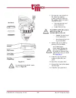
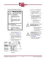
7. Install a new breakaway insulator into
the tip assembly nut so the
counterbores are facing up.
8. Orient the alignment pin in the tip
assembly so it is in-line with the
alignment hole in the breakaway
insulator.
9. Fasten the breakaway insulator to the
tip assembly using the (6) M3 SHCS
removed in step 4.
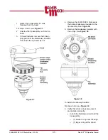
10. If necessary, replace the gas jet tip
11. Install the tip assembly according to
12.
IMPORTANT!
Verify beam centering according to
Adjust the beam as necessary
using the beam centering knobs.
See
It should not be necessary to make
any adjustments along the X-axis
or Y-axis. See
Figure 59
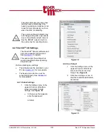
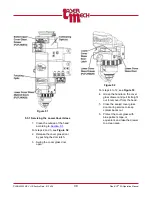
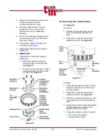
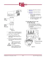
5.5 Servicing the Tip Assembly
To remove:
1. Unthread the tip assembly nut and
remove the tip assembly from the
head.
2. Verify both o-rings are present and
Figure 60
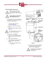
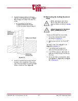
To install:
3. Verify that the alignment flat on the tip
assembly faces the front of the head
and the air blast.
4. Verify both o-rings are present and
5. Push the tip retainer assembly up until
it is centered on and flush against the
head.
6. Rotate the tip retainer assembly slightly
until the alignment pin seats in the
alignment hole in the head.
7. Thread the retainer nut onto the head.
Do not allow the aligned
components to rotate.