background image


5

Instruction Manual 

Hydraulic Pullers 

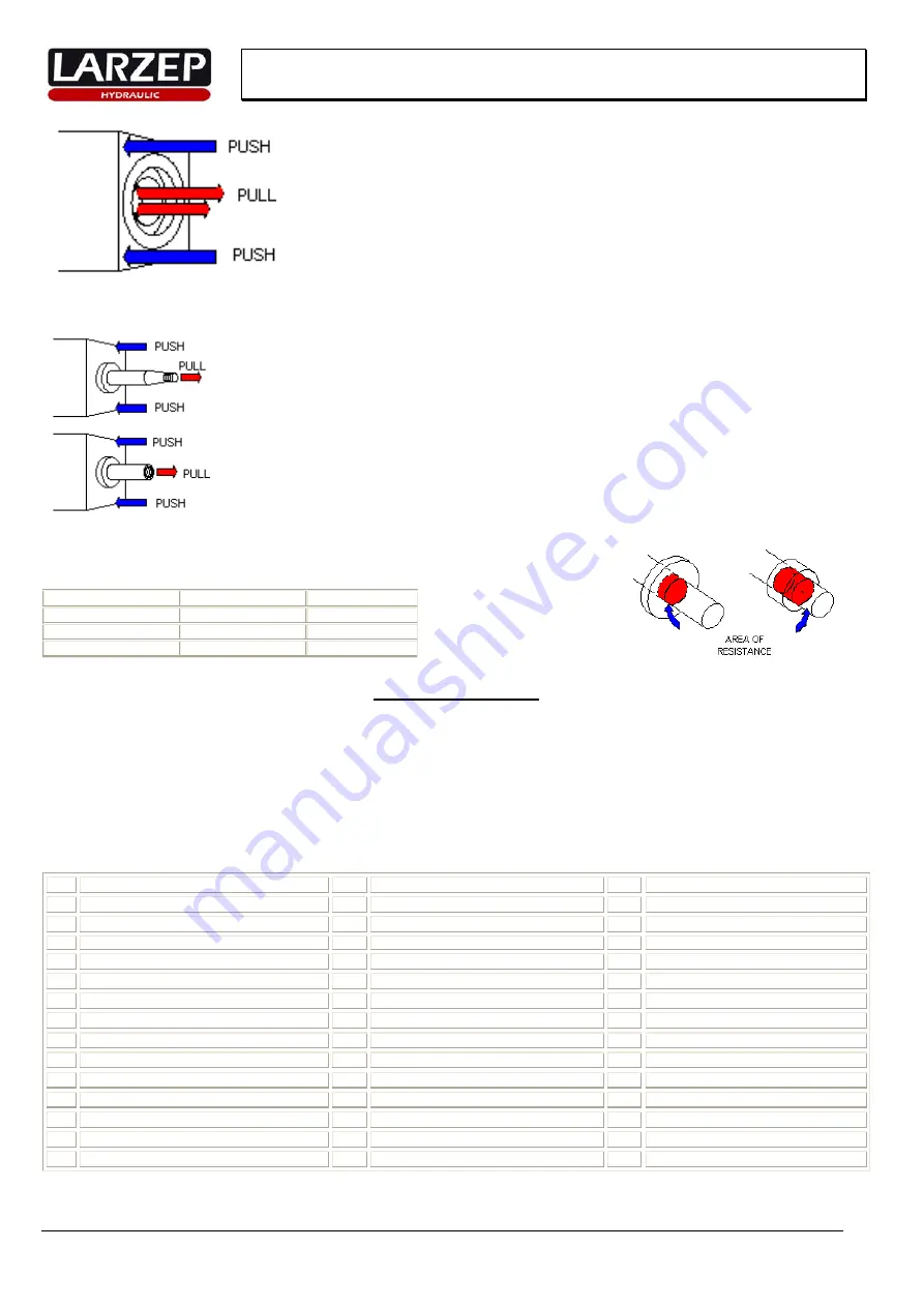
To grip and pull an internal bearing:


Place the (FI) Bearing Cup Puller inside the bearing to be pulled, check the puller is centred. 

Use the internal puller FI in combination with the FZ o FT models. 


To grip and pull a shaft from housing:


Fasten to the threaded male end of the shaft to pull while pushing against the housing. 
Use the thread of the shaft to tighten the puller and this way pull while pushing against the housing. 


How to choose the capacity of a puller 

For hydraulic pullers, the maximum 

force exerted in tons should be 7 times the diameter of the shaft in 

inches.


Shaft diam. in inches 

Shaft diam. in mm 

Cap. Puller in Tons

0" - 2" 

0 - 50 

20 

2" - 3 1/2" 

50 - 87 

30 

3 1/2" - 5 1/2" 

87 - 136 

50 


5. MAINTENANCE. 


o


All the maintenance operations must be done with depressurized equipment and disconnected hydraulic and electrically. 

o


Always use 

LARZEP

 original spare parts. 

o


In every use of the equipment make a visual inspection; check the oil level, damages in hydraulic part (scratched piston, thread, leaks, etc.), the condition 
of the accessories.(hoses, couplers, etc.)


o


Clean the equipment after each use and keep grease critical areas: threads, shafts, inside the roller, piston, etc. before store the equipment in the box.


o


In case of frequent use, replace periodically the hoses and couplers although they do not seem damaged.


o


Periodically (at least once to the year), replace the hydraulic oil of the tank by clean oil. 

o


The oil filling it’s made through the plug. Check the level with the dipstick placing the pump head down in vertical position. Use L

ARZEP AZ8901 oil. 

o


The maintenance operations or repairs that suppose the dismantling of the mechanical parts of the equipment (jack, cylinder or pump) must be done by 
specialist personnel. 


 PROBLEM 

 DIAGNOSIS 

 SOLUTION 

The piston of the cylinder does not advance. 

1.1 

Excess or lack of oil in the tank. 

1.1 

Check the level and refill. 


1.2 Clogged 

filter. 

1.2 Dismantle the pump and clean it. 


1.3 

Oil leak by the admission ball of the pump. 

1.3 

Repair the ball seat and replace the ball. 


1.4 

Pressure collar of the cylinder damaged. 

1.4 

Replace the detent. 


1.5 

Cup of the pump damaged. 

1.5 

Replace the collar. 


1.6 

Pressure relief valve of the pump unrated. 

1.6 

Rate the valve. 


1.7 

A bad connection of the hose. 

1.7 

Check the connection. 

The cylinder does not reach pressure. 

2.1 

Pressure collar of the cylinder damaged. 

2.1 

Replace the detent. 


2.2 

Leak by the ball of the action screw. 

2.2 

Repair the ball seat and replace the ball.


 2.3 

Oil leak by the admission ball of the pump. 

2.3 

Repair the ball seat and replace the ball.

The piston does not return. 

3.1 

Ball of the action screw pasted. 

3.1 

Release the screw and move the ball. 


3.2 

Jamming or twisted piston in the cylinder. 

3.2 

Repair or replace the piston. 


3.3 

Damaged spring in the cylinder. 

3.3 

Replace the spring. 


3.4 

Excess of oil in the tank. 

3.4 

Check the level. 

 
The solutions in black must be carried out by specialist personnel. 


Содержание FU0500

Страница 1: ...PULLER COMPLETE LARZEP S A LARZEP AUSTRALIA PTY LTD LARZEP GB LTD Avenida Urtiaga 6 104 Wedgewood Road 3 Commerce Way Leighton Buzzard 48269 MALLABIA SPAIN HALLAM VIC 3803 AUSTRALIA BEDS LU7 4RW UNITED KINGDOM Tel 34 943 171200 Tel 61 3 9796 3744 Tel 44 1525 377819 Fax 34 943 174166 Fax 61 3 9796 5964 Fax 44 1525 851990 e mail sales larzep com e mail sales larzep com au e mail sales larzep co uk w...

Страница 2: ...t the operation assure that there is not anybody exposed in the dangerous zone Check that the machine and the accessories has not suffered damages during the transport or installation Always use the equipment in well lit areas All the material of the installation must be in stable zone and the operator must foresee the movements of the application Choose the most suitable model for the application...

Страница 3: ...07 Hose AP2015 AP2015 AP2015 AP2015 AP2020 Gauge adaptor AZ1501 AZ1501 AZ1501 AZ1501 AZ1501 Gauge AV10008 AV10008 AV10008 AV10008 AV10008 Male coupling AZ3120 AZ3120 AZ3120 AZ3120 AZ3120 FU0500 M FU1000 M FU2000 M FU3000 M FU5000 M Mechanic Part Jaws FU0507 3 FU1007 3 FU2007 3 FU3007 3 FU5007 3 3 2 3 Jaw crosshead _ _ FU2008 FU3008 FU5008 2 Jaw crosshead _ _ FU2009 FU3009 FU5009 2 and 3 jaw crossh...

Страница 4: ...30 and 50 ton models Keep the spindle greased and cleaned Check the safety hole of the axle if it hasn t the hole use the shaft protector as supporting point Hold jaws slightly by tightening clamps bolts Place jaws in the lowest hole and centred respect the spindle The Jaws works perfectly whit a maximum angle of 10º Set the puller correctly adjust better the first alignment Tighten the spindle tu...

Страница 5: ...once to the year replace the hydraulic oil of the tank by clean oil o The oil filling it s made through the plug Check the level with the dipstick placing the pump head down in vertical position Use LARZEP AZ8901 oil o The maintenance operations or repairs that suppose the dismantling of the mechanical parts of the equipment jack cylinder or pump must be done by specialist personnel PROBLEM DIAGNO...

Страница 6: ...6 Instruction Manual Hydraulic Pullers 6 DECLARATION OF CONFORMITY ...

Страница 7: ... 50 400 230 580 Jaw puller Capacity Tn A max mm B max mm 5 230 240 10 350 305 20 480 350 30 580 393 50 920 690 Bearing cup puller Capacity Tn A max mm B max mm B min mm 10 115 145 40 20 115 145 40 30 150 240 60 50 150 240 60 Bearing puller Capacity Tn A max mm A min mm B mm D 5 110 10 130 5 8 UNF 18 10 110 10 130 5 8 UNF 18 20 130 25 150 5 8 UNF 18 30 250 35 260 1 UNF 14 50 330 50 300 1 1 4 UNF 12...

Страница 8: ...F 18 3 4 UNF 16 20 FU2023 336 19 5 30 25 5 8 UNF 18 3 4 UNF 16 30 FU3022 592 25 4 35 40 1 UNF 14 1 UNF 14 30 FU3023 328 25 4 35 40 1 UNF 14 1 UNF 14 50 FU5022 820 31 6 43 45 1 1 4 UNF 12 1 1 4 UNF 12 50 FU5023 504 31 6 43 45 1 1 4 UNF 12 1 1 4 UNF 12 Gross crosshead LARZEP Capacity ton A B C D FU0517 5 210 35 35 15 FU1017 10 280 40 40 20 FU2017 20 370 57 57 20 FU3017 30 480 77 5 77 5 26 FU5017 50 ...

Отзывы: