

3
Instruction Manual
Bench Press with Electric Pump “ECE01113”
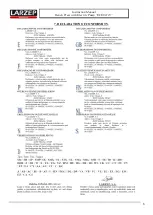
HYDRAULIC MOTORPUMP. REF: HAM7224
MODEL
HAM7224
Tank capacity
5 Litros útiles.
Volume in low pressure. Approaching
4 Litros/min
Volume in high pressure. Working.
0.36 Litros /min
Maximum pressure.
700 Kg/cm
Control valve
Manual Aluminio: 3 vías, 3 posiciones.
Motor
0, 75 kW a Tensión: 400V. 50Hz.3ph.
FRAME: MECHANICAL-WELDED
MODEL
ECE01113
Working height (mm)
352 mm
Working width (mm)
350 mm
Weight (Kg)
75 Kg
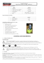
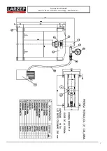
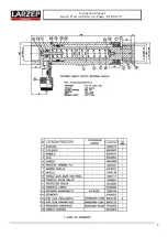
DESCRIPTION POWERPACK HAM7224 (See the figure).
The motor pump has the following part:
3. ESSENTIAL SAFETY REQUIREMENTS.
3.1
GENERAL CONSIDERATIONS
DANGEROUS AREA
The speed of the hydraulic cylinder during its extension is less than 30 mm/second. Therefore then machine should be considered by the application of ANNEX V of
the Declaration of CE Conformity.
Operators standing in the dangerous area around the machine should protect their feet, faces and hands from metal pieces being ejected during pressing.
Feet protection
Face protection
Hands protection
Used materials and components are not dangerous for the health and safety of operators. The hand pump contains LARZEP hydraulic oil ISO: HV46.
3.2
COMANDS
The cylinder advances when we act over the powerpack, push the general swicht (1-0) of the electrical cabinet or circuit motor breaker box.
To stop the motor we must push the red button.
We have to check the sense of the motor turn, it must be the same as the narrow labelled in the motor protector, if it does not coincide swap two cables between in
the terminal.
The hose connection is made; if not, the manual distributor valve have two outlets for the connection. The outlet labelled with “A” is the one to connect, the other
outlet labelled with “X” must be corking.
The operating of the distributor valve: If we act over the valve and we put it in “A” position, the cylinder will advance. When we put the valve in “T” position, the
cylinder will return and finally when the valve is in “C” position the pressure will be maintained.
Metal tank with oil level.
Metal lid, support for the entire hydraulic circuit.
Electric motor with corresponding coupling.
Hydraulic piston pump with filter.
Transportation plug and ventilation plug (plastic bag).
Pressure meter connection.
Motor circuit breaker box.
Manual distributing valve with 3/8 NPT outputs.
Internal safety valve adjusted to 700 bar.
Adjustable external pressure regulating valve: 0-700 bar.
Due to the
FUNCTIONAL REASONS
it is considered to be the space between the columns, the bed and the hydraulic cylinder piston.
Due to the
MATERIAL PRESSED
it is supposed to be surrounding area to the machine in case of metal parts being ejected during pressing.
HIDRAULIC OIL IS TOXIC IF IT ENTERS THE BLOODS STREAM. NEVER PLACE A FINGER OVER ANY ORIFICE OR LEAK,
WHICH COULD BE PRESSURIZED, SUCH AS THE HYDRAULIC LINE, AS THIS COULD CAUSE OIL TO BE INJECTED INTO BLOOD
STREAM.


