
1W UHF AMPLIFIER ASSEMBLY
PUB99-92 rev 1: June 19, 2000
92-1
1
W UHF Amplifier
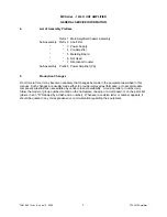
Contents:
Part
Topic
Page
1
Amplifier Chassis Description ........................................................................................ 92-1
2
Pre-Amplifier Module...................................................................................................... 92-2
3
PA Module...................................................................................................................... 92-2
4
Directional Coupler......................................................................................................... 92-3
5
Metering Board .............................................................................................................. 92-3
6
Power Supply ................................................................................................................. 92-4
7
Basic Maintenance/Replacement Parts ......................................................................... 92-5
8
Parts List ...................................................................................................................... 92-12
List of Figures:
Figure
Title
Drawing Reference
92-1 Chassis Assembly Diagram .....................................................................................40D2180G3
92-2 Wiring and Block Diagram.............................................................................................20B2482
92-3 Pre-Amp Module Assembly and Schematic Diagrams............................................. 10A1453G7
10A1453sheet13
92-4 PA Module Assembly ............................................................................................... 21B1324G2
92-5 PA PCB Assembly ................................................................................................... 21B1334G1
92-6 PA Module Schematic................................................................................................ 21B1334S
92-7 Directional Coupler Assembly ..................................................................................10A2086G1
92-8 Metering Board Assembly ........................................................................................ 20B1235G5
92-9 Metering Board Schematic............................................................................................20B2448
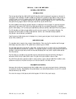
1.0
Amplifier Chassis Assembly 40D2180G3:
Figure 92-1.
The Amplifier Chassis consists of a standard 19" rack mounted 3.5”, 2RU enclosure containing a line filter,
power supply, two amplifier module assemblies, a directional coupler, metering board, and a metering
panel. Its basic part number is 40D2180.
The amplifier modules are broadband, thus covering the entire UHF television spectrum ranging from
470MHz to 860MHz.
117VAC to the amplifier chassis comes in via a fused line filter, 2LF1. Pressing the ON/OFF switch to the
ON position (UP) applies AC to the primary of the power supply transformer, thus, applying DC power to
the amplifier stages.
Metering is achieved using a directional coupler which samples the RF signal. It is fed to a peak detection
metering board which then displays the corresponding power level on the front panel analog meter.
The chassis is wired according to the wiring diagram, 20B2482, shown on Figure 92-2.
Chassis parts lists are provided on the last pages of this manual. The circled numbers seen on the
assembly drawing correspond to the "symbol" item numbers on the parts list.


