4: Configuration Using Web Manager
3. When you are finished, click the
OK
button.
4. On the main menu, click
Apply Settings
.
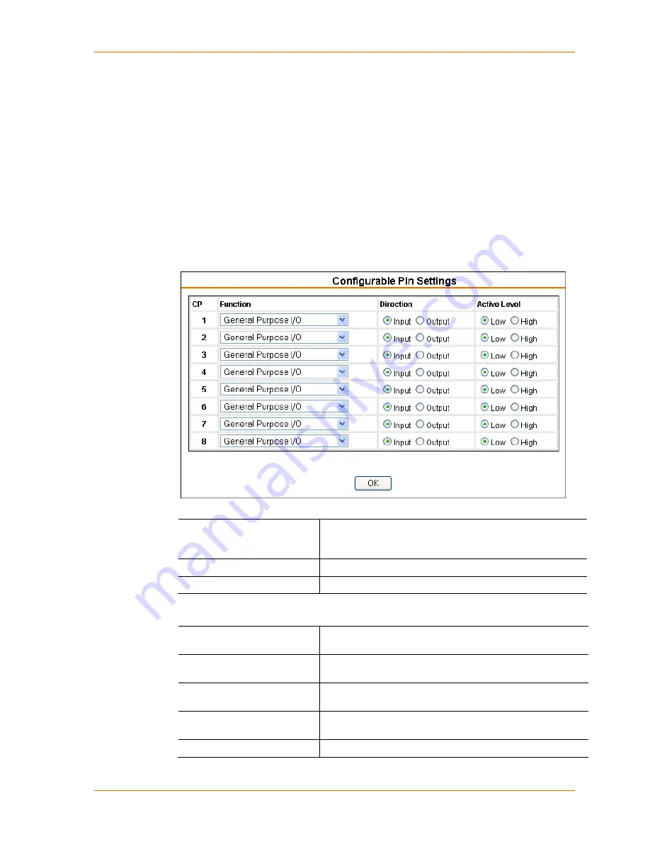
Configurable Pin Settings
There are eight configurable hardware pins on the xPico unit. For each pin, configure
the pin function, communication direction, and activity level. For more information,
see
9 GPIO Interface
.
To configure the xPico’s Configurable Pins:
1. On the main menu, click
Configurable
Pins.
The Configurable Pins page opens.
Figure 4-9. Configurable Pins Settings
2. Configure or modify the following fields for each pin:
Function
From the drop-down menu, select the purpose of the
specified pin. See
Configurable Pin Functions
(below) for
a description of each available function.
Direction
Select whether the pin inputs or outputs.
Active Level
Select the signal active level (Low or High).
Configurable Pin Functions
General Purpose I/O
Monitors input using the 77F0 port or controls output by the
77F0 port.
Modem Ctrl Channel 1 In
For DTE device configuration this would be the DCD control
line.
Modem Ctrl Channel 1 Out
For DTE device configuration this would be the DTR control
line.
RS485 Select Channel 1
Optional control signal that enables toggling between RS232
and RS485 on OEM hardware design.
RS485 2-Wire Channel 1
Optional control signal that enables toggling between RS485
xPico User Guide
32
Содержание xPico
Страница 1: ...xPico User Guide Part Number 900 618 Revision B January 2013 ...
Страница 28: ...4 Configuration Using Web Manager Figure 4 7 TCP Connection Settings xPico User Guide 28 ...
Страница 78: ...A Binary to Hexadecimal Conversions 4 Click Hex The hexadecimal value displays xPico User Guide 78 ...


