background image

www.lanpro.com

Wireless - Equipment - 5.8 GHz - LP-289ai 123 Manual for PtP and PtMP Modes setup

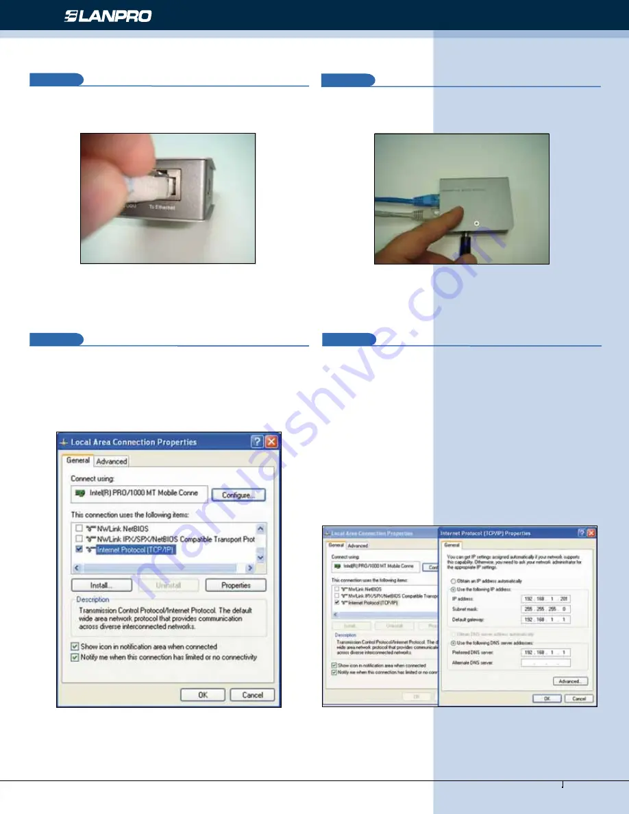
Connect a cable now from the PoE port: 

To Ethernet

 to the 

Switch or PC as shown in figure 3.

Figure 3

3

3

Connect power to the PoE as shown in figure 4.

4

In  figure  5  go  to  your  NIC  card    properties  and  select: 

Internet Protocol

, select: 

Properties

.

Figure 4

5

Figure 5

6

In the window shown in figure 6, select: 

Use the following 

IP  address

  and  next  input  an  IP  address  in  the  default 

range  of  the  LP-289ai.  In  this  example,  we  have  selected 
address 192.168.1.201, the LP-289ai has a default address 
of 192.168.1.1, input now in: 

Subnet mask

 255.255.255.0 

and in the: 

Default gateway

 the destination router address; 

in the: 

DNS

 you should input your Service provider´s 

DNS


or the destination router’s IP address which will provide you 
with  internet  service,  this  will  permit  any  queries  to  reach 
the router of the destination network.

Figure 6

Содержание LP-289ai

Страница 1: ...Wireless Equipment www lanpro com LP 289ai 123 Manual for PtP and PtMP Modes setup LP289ai_M123_ENF02W LP 289ai 123 Manual for PtP and PtMP Modes setup...

Страница 2: ...hown in figure 1 in which 3 equipment in a PtMP connection will serve as a guide for you to their configuration please remember that each equipment has a unique MAC address that you will require later...

Страница 3: ...the window shown in figure 6 select Use the following IP address and next input an IP address in the default range of the LP 289ai In this example we have selected address 192 168 1 201 the LP 289ai h...

Страница 4: ...7 Open your preferred browser and input the default address 192 168 1 1 please see figure 7 4 8 In the validation window of figure 8 select Continue to this website Figure 7 Figure 8 9 In the window o...

Страница 5: ...e 11 in the Wireless setup men proceed to select WDS Settings input in the Remote Mac Address the Mac addresses of the destination equipment as shown please refer to the diagram of figure 1 It is very...

Страница 6: ...he equipment you wish to communicate to Additionally please change the IP address as per the diagram by going to figure 15 in the menu System Setup select IP Settings change the IP and select Apply th...

Страница 7: ...ure 17 a Figure 17 a b Enter the LP 289ai and in the window shown in figure 17b check the option Connections verify that all the LP 289ai are connected Figure 17 b c In the window shown in figure 17 c...

Страница 8: ...20 In the window of figure 20 input the old password in Current Password and the new password in New Password repeat it in Repeat New Password and select Apply Figure 19 Figure 20 8 19 It is recommend...

Отзывы: