


6
Introduction
Chapter 2
Network Application Platforms
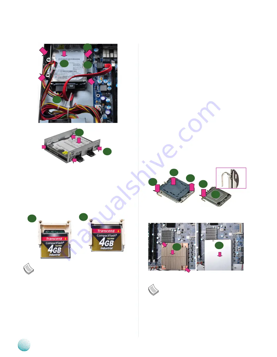
Remove the CPU socket cap.
1.
Press the load lever and release it from the retention
2.
tab.
Lift the load lever and then the plate.
3.
Align the cut-out of the CPU and the notch on the
4.
socket. The CPU should fit perfectly into the socket.
Note that the CPU fits in the socket in only one
direction.
Close the plate and push the load lever to lock it back
5.
to the retention tab.
Peel off the sticker on the CPU to expose the thermal
6.
compound.
Put the heat sink on top of the installed CPU, match
7.
the screws with the screw holes on the board. Fasten
two screws which are opposite to each other at a time
and then the other two. It is easier this way because of
the springiness of the bracket.
Place the heat sink cover on top of the installed heat
8.
sink and screw the two screws to fasten it on the case.
Note:
The CPU heat sink could only be installed in only
1.
one direction as shown in the picture.
To protect the CPU socket pins, retain the CPU
2.
cap when the CPU is not installed.
2
3
5
4
1
Installing a CompactFlash Card
FW-7580 provides one CompactFlash slot(CF1). Follow the
procedures bellow for installing a CompactFlash card.
Align CompactFlash card and the card slot with the
1.
arrow pointing toward the connector.
Push the card to insert into the connector.
2.
Note: The Compact Flash Card has a jumper
setting (J2) to set itself as a primary or slave device It is
only useful when there are other storage devices such as
a CD-ROM installed in the system which is not applicable
in the FW-7580. For more details, please refer to
.
CPU and the Heat Sink Installation
The FW-7580 sever system is powered by the MB-75807580
sever board, which comes with one ZIF type LGA775 CPU
socket.
Follow the procedures bellow for installing a CPU
1
2
2
3
8
7
1
4
5
6