background image


PEXNSD01-040709 

Version 1.0 

Printed and published in Taiwan 

Содержание FW-7650 Series

Страница 1: ...FW 7650 Series 19 1U Intel Pentium4 Celeron Rackmount Network Security Platform User s Manual ...

Страница 2: ...smitted in any form or by any means electronic mechanical photocopying recording or otherwise without the formal consent from Lanner Trademark Acknowledgments All products and or brand names stated in this publication are the trademarks of their rightful and associated companies Radio Frequency Emissions Notice This equipment has been tested and found to comply with the digital device limits pursu...

Страница 3: ...bject of any kind into this product through openings or empty slots as you may damage parts Do not attach the power supply cabling to building surfaces Do not allow anything to rest on the power cabling or allow it to be abused by persons walking on it Distance your working area from moist floors ungrounded power extension cables and unavailable safety grounds Avoid installation of this product du...

Страница 4: ...rinc com About this Manual This target audience of this manual includes users administrators and technicians This publication is a useful reference when installing configuring operating and managing the FW 7650 This breakdown and short descriptions of this manual s contents are as follows Chapter 1 Introduction provides an overview of the FW 7650 19 1U Rackmount network security appliance includin...

Страница 5: ...2x4 Header 2 54mm 7 PSA1 20 Pin ATX Power Connector 7 PSA1 20 Pin ATX Power Connector 8 PS4P1 4 Pin Power Connector P4 4P Male 8 KPA1 LCM Keypad 8 LCMA1 LCM CONNECTOR 8 VGAB1 External VGA Connector 12 Pin Header 9 IDEA1 IDE Interface Connector 44Pin 2 0mm Pitch Header 9 PLRS1 Power LED HD LED Reset Speaker Connector 11 Pin 2 54mm 10 FDCA1 Floppy Interface Connector 34 Pin Header 10 CF1 Compact Fla...

Страница 6: ...h Status 40 3 10 Load Optimized Defaults 41 3 11 Supervisor User Password Setting 41 3 12 Save and Exit Setup 41 3 13 Exit Without Saving 42 Appendix A 43 Power Supply 43 Appendix B 44 Watchdog Timer 44 A p p e n d i x C 46 Console Redirection 46 A p p e n d i x D 47 LCD Module and Key Pad For FW 7650 47 Terms and Conditions 49 Warranty Policy 49 RMA Service 49 ...

Страница 7: ...hich provide full functionality and performance to be used exactly where you need it as well In addition one ATA mode CompactFlash type II socket used in installing OS avoiding service disruption caused by hard disk s mechanical magnetic failures The FW 7650 has a Mini PCI slot users can expand their specifications and performance by simply adding add on cards to the slot The FW 7650 is a powerful...

Страница 8: ...ernet Controller Colay with 82551QM B Four Intel 82551QM 10 100 Mb Ethernet Controller SSD Two CompactFlash TypeII Socket I O Interface One DB 9 RS 232 connector Expansion Slot One Mini PCI slot RTC Internal RTC with LI battery Power 200W ATX Power Supply Mechanical Environmental Form Factor 19 1U Rackmount Operating Temperature 0 o C 40 o C Storage Temperature 20 o C 70 o C Humidity 5 95 RH non c...

Страница 9: ... Network security Platform Console cable 1 8 meters long cross over Ethernet cable 1 8 meters long straight through Ethernet cable Face panel name plate label Power cable Drivers and User s Manual CD Screw Set Slid Bracket Set If you find anything missing or damaged promptly contact your dealer for assistance ...

Страница 10: ...B X71 is the system board bundled with the FW 7650 Network security platform The succeeding sections list all MB X71 related jumper settings and connector pin assignments 1 4 1 Board Layout Figure 3 MB X71 Jumpers and Connectors ...

Страница 11: ...Connector LANA1 2 Type 1 RJ 45 LANA3 6 Type 1 RJ 45 COM1 RS232 Serial Port 1 Connector D Sub PKMB1 PS 2 Keyboard Mouse Connector 2x4 Header 2 54mm PSA1 20 Pin ATX Power Connector PS4P1 4 Pin Power Connector P4 4P Male KPA1 LCM Keypad LCMA1 LCM CONNECTOR VGAB1 External VGA Connector 12 Pin Header IDEA1 IDE Interface Connector 44 Pin 2 0mm Pitch Header IDEB1 IDE Interface Connector 40 Pin 2 54mm Pit...

Страница 12: ...e Master 2 3 Default CMOS1 Clear CMOS Data CMOS1 Description 1 2 Normal Default 2 3 Clear CMOS FAN1 3 3 Pin FAN Connector Pin No Description 1 Ground 2 12V 3 FAN Status LANA1 2 Type 1 RJ 45 Description Pin No Fast Ethernet Giga Ethernet 1 TX MD0 2 TX MD0 3 RX MD1 4 T45 MD2 5 T45 MD2 6 RX MD1 7 T78 MD3 8 T78 MD3 LANA1 2 ...

Страница 13: ... 1 Data Carrier Detect DCDA 2 Receive Data RXDA 3 Transmit Data TXDA 4 Data Terminal Ready DTRA 5 Ground GND 6 Data Set Ready DSRA 7 Request To Send RTSA 8 Clear To Send CTSA 9 Ring Indicator RIA PKMB1 PS 2 Keyboard Mouse Connector 2x4 Header 2 54mm Pin No Description Pin No Description 1 KBCLK 2 GND 3 NC 4 KBDATA 5 NC 6 MSDATA 7 MSCLK 8 VCC COMA1 ...

Страница 14: ... Power Good 18 5V 9 Stand By 5V 19 5V 10 12V 20 5V PS4P1 4 Pin Power Connector P4 4P Male Pin No Description 1 GND 2 GND 3 12V 4 12V KPA1 LCM Keypad Pin No Description 1 KPA1 2 KPA2 3 KPA3 4 KPA4 LCMA1 LCM CONNECTOR Pin No Description Pin No Description 1 VCC 2 PGND 3 LSTIN 4 VEE 5 LAFD 6 LINIT 7 LPD1 8 LPD0 9 LPD3 10 LPD2 11 LPD5 12 LPD4 13 LPD7 14 LPD6 15 LCD 16 VCC ...

Страница 15: ...ader Pin No Description Pin No Description 1 Reset 2 Ground 3 Data 7 4 Data 8 5 Data 6 6 Data 9 7 Data 5 8 Data 10 9 Data 4 10 Data 11 11 Data 3 12 Data 12 13 Data 2 14 Data 13 15 Data 1 16 Data 14 17 Data 0 18 Data 15 19 Ground 20 NC 21 DMA REQ 22 Ground 23 IOW 24 Ground 25 IOR 26 Ground 27 IOCHRDY 28 Ground 29 DMA ACK 30 Ground 31 Interrupt 32 NC 33 SA 1 34 NC 35 SA 0 36 SA 2 37 HDC CS 0 38 HDC ...

Страница 16: ...nnector 34 Pin Header Pin No Description Pin No Description 1 Ground 2 Density Select 3 Ground 4 NC 5 Ground 6 DS1 7 Ground 8 Index 9 Ground 10 Motor Enable A 11 Ground 12 Drive Select B 13 Ground 14 Drive Select A 15 Ground 16 Motor Enable B 17 Ground 18 Direction 19 Ground 20 Step 21 Ground 22 Write Data 23 Ground 24 Write Gate 25 Ground 26 Track 0 27 Ground 28 Write Protect 29 NC 30 Read Data 3...

Страница 17: ... 29 DATA13 5 DATA6 30 DATA14 6 DATA7 31 DATA15 7 CE1 32 CE2 8 A10 33 VS1 9 OE 34 IOR 10 A9 35 IOW 11 A8 36 WE 12 A7 37 READY 13 CFVCC3 38 CFVCC3 14 A6 39 CSEL 15 A5 40 VS2 16 A4 41 RESET 17 A3 42 WAIT 18 A2 43 INPACK 19 A1 44 REG 20 A0 45 DASP 21 DATA0 46 DIAG 22 DATA1 47 DATA8 23 DATA2 48 DATA9 24 WP 49 DATA10 25 CD2 50 GND ...

Страница 18: ...0 LED 15 Lan2 1G LED 16 Lan2 1G LED 17 Lan3 Link Active LED 18 Lan3 Link Active LED 19 Lan3 100 LED 20 Lan3 100 LED 21 Lan3 1G LED 22 Lan3 1G LED 23 Lan4 Link Active LED 24 Lan4 Link Active LED 25 Lan4 100 LED 26 Lan4 100 LED 27 Lan4 1G LED 28 Lan4 1G LED 29 Lan5 Link Active LED 30 Lan5 Link Active LED 31 Lan5 100 LED 32 Lan5 100 LED 33 Lan5 1G LED 34 Lan5 1G LED 35 Lan6 Link Active LED 36 Lan6 Li...

Страница 19: ...ata 9 7 Data 5 8 Data 10 9 Data 4 10 Data 11 11 Data 3 12 Data 12 13 Data 2 14 Data 13 15 Data 1 16 Data 14 17 Data 0 18 Data 15 19 Ground 20 NC 21 DMA REQ 22 Ground 23 IOW 24 Ground 25 IOR 26 Ground 27 IOCHRDY 28 Ground 29 DMA ACK 30 Ground 31 Interrupt 32 NC 33 SA1 34 PD80P SD80P 35 SA0 36 SA2 37 HDC CS0 38 HDC CS1 39 HDD Active LED 40 Ground ...

Страница 20: ...LP 15 CHSGND 16 RESERVED 17 INT B 18 5V 19 3 3V 20 INT A 21 RESERVED 22 RESERVED 23 GROUND 24 3 3VAUX 25 CLK 26 RST 27 GROUND 28 3 3V 29 REO 30 GNT 31 3 3V 32 GROUND 33 AD31 34 PME 35 AD29 36 RESERVED 37 GROUND 38 AD30 39 AD27 40 3 3V 41 AD25 42 AD28 43 RESERVED 44 AD26 45 C_BE 3 46 AD24 47 AD23 48 IDSEL 49 GROUND 50 GROUND 51 AD21 52 AD22 53 AD19 54 AD20 55 GROUND 56 PAR 57 AD17 58 AD18 59 C_BE 2...

Страница 21: ... 84 AD9 85 AD8 86 C_BE 0 87 AD7 88 3 3V 89 3 3V 90 AD6 91 AD5 92 AD4 93 RESERVED 94 AD2 95 AD3 96 AD0 97 5V 98 RESERVED WIP 99 AD1 100 RESERVED WIP 101 GROUND 102 GROUND 103 AC_SYNC 104 M66EN 105 AC_SDATA_IN 106 AC_SDATA_OUT 107 AC_BIT_CLK 108 AC_CODEC_ID0 109 AC_CODEC_ID1 110 AC_RESET 111 MOD_AUDIO_MON 112 RESERVED 113 AUDIO_GND 114 GROUND 115 SYS_AUDIO_OUT 116 SYS_AUDIO_IN 117 SYS_AUDIO_OUT GND ...

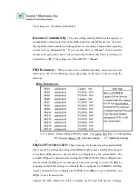
Страница 22: ...IO N A The speed of LAN is 10Mbit s Green The speed of LAN is 100Mbit s Ethernet Ports Orange The speed of LAN is 1000Mbit s On When LAN is connected Ethernet Ports Link ACT Green Orange Flash When Data is accessing Lanner provide the LED status sample in the path FW 7650_MB X71 LED_Sample_Code Console Port via the console port cable this connector attaches FW 7650 to the host PC The Default baud ...

Страница 23: ...he Power Switch and the system will be power on Faulty or improper use of the power adaptor may cause permanent damage to the power supply and the FW 7650 Plug the adaptor to an electrical wall outlet that matches its specifications Blowhole Power Switch Power Socket ...

Страница 24: ... 1 Hardware Installation Guide Inside of FW 7650 CPU Installation Step 1 Locate the ZIF socket and open it by first pulling the lever of socket upward Step 2 Insert the CPU into the socket Please keep the lever right angle when inserting CPU Step 1 Step 2 ...

Страница 25: ... Push the lever down to close the socket Step 5 Please take the screw off Step 6 Please find a cooler Fan Heat Sink within the packing attach it into the CPU Step 7 Finally connect the fan cable to the CPU fan header System Memory Step 1 Open latches of DIMM socket Step 2 Insert the RAM module into the DIMM socket Step 3 Step 4 Step 5 Step 6 ...

Страница 26: ...he mobile rack Step 3 Remove the mobile rack straight and smooth How to Remove the Hard Disk Bay Step 1 Use screwdriver to remove four screws on the cover Step 2 Pick up the cover Step 3 Connect the 44pin cable and insert a 2 5 hard disk Step 4 Screw the 2 5 hard disk from the bottom of the mobile rack you may find the four screws within the packing Step 1 Step 2 Step 3 Step 4 ...

Страница 27: ...ard into the slot carefully as shown in the picture Installing the Mini PCI Card Step 1 Insert the PCI expansion card into the mini PCI slot at 45 degree Step 2 Push down the PCI expansion card and the PCI expansion card is clicked together completely with the PCI expansion slot Step 1 Step 1 Step 2 Step 5 Step 6 ...

Страница 28: ...vated in one of two ways 1 By pressing Del immediately after switching the system on or 2 By pressing the Del key when the following message appears briefly at the bottom of the screen during the POST Power On Self Test Press DEL to enter SETUP If the message disappears before you respond and you still wish to enter Setup restart the system to try again by turning it OFF then ON or pressing the RE...

Страница 29: ...g through the menu bar Use the left and right arrow keys to choose the menu you want to be in To display a sub menu use the arrow keys to move the cursor to the sub menu you want Then press Enter A pointer marks all sub menus Getting Help Press F1 to pop up a small help window that describes the appropriate keys to use and the possible selections for the highlighted item To exit the Help Window pr...

Страница 30: ... menu for basic system configurations Advanced BIOS Features Use this menu to set the Advanced Features available on your system Advanced Chipset Features Use this menu to change the values in the chipset registers and optimize your system s performance Integrated Peripherals Use this menu to specify your settings for integrated peripherals PnP PCI Configuration This entry appears if your system s...

Страница 31: ... to CMOS and exit setup Exit Without Saving Abandon all CMOS value changes and exit setup 3 3 Standard CMOS Features The items in Standard CMOS Setup Menu are divided into 9 categories Each category includes no one or more than one setup items Use the arrow keys to highlight the item and then use the PgUp or PgDn keys to select the value you want in each item ...

Страница 32: ...ut Keyboard All but Diskette All but Disk Key Select the situation in which you want the BIOS to stop the POST process and notify you Base Memory N A Displays the amount of conventional memory detected during boot up Extended Memory N A Displays the amount of extended memory detected during boot up Total Memory N A Displays the total memory available in the system IDE Adapters The IDE adapters con...

Страница 33: ... by a disk checking program Access Mode CHS LBA Large Auto Choose the access mode for this hard disk Cylinder Min 0 Max 65535 Set the number of cylinders for this hard disk Head Min 0 Max 255 Set the number of read write heads Precomp Min 0 Max 65535 Warning Setting a value of 65535 means no hard disk Landing zone Min 0 Max 65535 Sector Min 0 Max 255 Number of sectors per track 3 4 BIOS Features S...

Страница 34: ...Floppy Drive The default setting is Disabled This setting gives you an option to swap A and B floppy disks Normally the floppy drive A is the one at the end of the cable and drive B is at the other end If you set this option to Enabled the Drive A will function as Drive B and vice versa under the DOS Floppy Disk Access Control This option specifies the read write access that is set when booting fr...

Страница 35: ...ilure This gives you an opportunity to move data to a safe place before the hard disk becomes offline Settings Enabled and Disabled Video BIOS Shadow The default setting is Enabled which will copy the VGA display card BIOS into system DRAM to improve performance C8000 CBFFF Shadow to DC000 DFFFF Shadow The default setting for the shadow feature is Disabled When enabled the ROM with the specific ad...

Страница 36: ...IMM clock equal to 66MHz SDRAM Cycle Length This item allows you to select the SDRAM cycle length The settings are 2 or 3 CAS latency Time When synchronous DRAM is installed the number of clock cycles of CAS latency depends on the DRAM timing Do not reset this field from the default value specified by the system designer DRAM RAS to CAS Delay This field lets you insert a timing delay ...

Страница 37: ...ormance However if any program writes to this memory area a system error may result The settings are Enabled and Disabled Video BIOS Cacheable Selecting Enabled allows caching of the video BIOS ROM at C0000h to C7FFFh resulting in better video performance However if any program writes to this memory area a system error may result Memory Hole At 15M 16M You can reserve this area of system memory fo...

Страница 38: ...ace if you install a primary and or secondary add in IDE interface IDE Prefetch Mode The onboard IDE drive interfaces supports IDE prefetching for faster drive accesses If you install a primary and or secondary add in IDE interface set this field to Disabled if the interface does not support prefetching The settings are Enabled and Disabled USB Controller Select Enabled if your system contains a U...

Страница 39: ...t and AGP Slot Onboard FDD Controller Select Enabled if your system has a floppy disk controller FDC installed on the system board and you want to use it If you install add in FDC or the system has no floppy drive select Disabled in this field The settings are Enabled and Disabled Onboard Serial Port 1 Select an address and corresponding interrupt for the first and second serial ports The settings...

Страница 40: ... you system to most effectively save energy while operating in a manner consistent with your own style of computer use This category allows you to select the type or degree of power saving and is directly related to the following modes 1 HDD Power Down 2 Doze Mode 3 Suspend Mode ...

Страница 41: ...ng Doze mode the monitor will be turned off Standby During Standby mode the monitor will be turned off Suspend During Suspend mode the monitor will be turned off Video Off Method This determines the manner in which the monitor is blanked The default setting is V H SYNC Blank V H SYNC Blank This selection will cause the system to turn off the vertical and horizontal synchronization ports and write ...

Страница 42: ...tings PnP OS Installed When set to Yes BIOS will only initialize the PnP cards used for booting VGA IDE SCSI The rest of the cards will be initialized by the PnP operating system like Windows 95 or 98 When set to No BIOS will initialize all the PnP cards So for non PnP operating system DOS Netware this option must set to Yes Reset Configuration Data Normally you leave this field Disabled Select En...

Страница 43: ...errupt as one of the following types depending on the type of device using the interrupt IRQ3 4 5 7 9 10 11 14 15 These items specify the bus where the specified IRQ line is used The settings determine if AMIBIOS should remove an IRQ from the pool of available IRQs passed to devices that are configurable by the system BIOS The available IRQ pool is determined by reading the ESCD NVRAM If more IRQs...

Страница 44: ...ned by reading the ESCD NVRAM If more DMAs must be removed from the pool the end user can reserve the DMA by assigning an ISA EISA setting to it Reserved Memory Size This option specifies the size of the memory area reserved for legacy ISA adapter cards The settings are Disabled 16K 32K or 64K The optimal and Fail Safe default settings are Disabled Reserved Memory Address This option specifies the...

Страница 45: ...ld at Disabled The settings are Enabled Disabled PCI Latency Timer PCI Clocks This option is used to control PCI latency timer period follow PCI clocks Based on PCI specification 2 1 or later and PCI bus frequency in system user can select different timer to meet their PCI bus environment ...

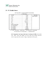
Страница 46: ... Status CPU Temperature Fan1 Speed Fan2 Speed Fan2 Speed VCORE 2 5 3 3V 5V 12V These items display the current status of all monitored hardware devices components such as system voltages temperatures and fan speeds ...

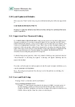
Страница 47: ...o the main screen Remember that when you use this feature the Security Option line in BIOS FEATURES SETUP will determine when entering the password will be required To disable the password press the Enter key instead of entering a new password when the Enter Password in the dialog box appears A message will appear confirming that the password is disabled If you have set both supervisor and user pa...

Страница 48: ...ing Enter on this item asks for confirmation Quit without saving Y N Y This allows you to exit Setup without storing in CMOS any change The previous selections remain in effect This exits the Setup utility and restarts your computer ...

Страница 49: ...se Max 5V 3 25 00 5 1 50mV 12V 2 8 00 7 1 100mV 5V 0 05 0 50 10 1 120mV 12V 0 05 0 50 10 1 150mV 3 3V 1 1 4 5 1 50mV 5VSB 0 1 1 5 5 1 50mV Feature Active PFC full range MEET IEC 1000 3 2 CLASS D TEMPERATURE RANGE OPERATING 00C 500C EMI NOISE FILTER FCC CLASS B CISPR22 CLASS B SAFETY UL 1950 CSA 22 2 NO 950 TUV IEC 950 Remote on off control Cooling ONE 40 mm DC Fan 3 3V 5V Remote sensing Extend AC ...

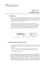
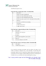
Страница 50: ...and the processor s reset signal is asserted The processor will be restarted as if a human operator had cycled the power Detail Register Bit and Pin Descriptions A watchdog action consists of a series of watchdog instructions A watchdog instruction is the operation on a register region This section describes the detail register in LPC I O IT8712F The feathers of Watch dog timer in LPC I O IT8712F ...

Страница 51: ...cond 0 Minute 6 WDT output through KRST pulse enable 5 4 Reserved 3 0 Select the interrupt level for WDT Watch Dog Timer Time Out Value Register Index 73h Default 00h Bit Description 7 0 WDT time out value 7 0 If you enable the watch dog the hardware timer will reboot your system if your software encounters an unexpected error or stops responding The watch dog timer period from enable to reset was...

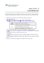
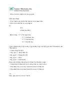
Страница 52: ... absent Auto If keyboard is plug in the Controller board the Console Redirection will not display BIOS screen on remote client If keyboard is not plug in the Controller board the Console Redirection will display BIOS screen on remote client 3 Configure Console redirection on client system This example is for Windows platform i Click the Start button point to programs Æ Accessories Æ Communications...

Страница 53: ...de How to install the driver in Windows 2000 XP In the W2K_WinXP folder LCM SYS Æ Windows 2000 XP Driver LCM REG Æ Windows 2000 XP Registry 1 In Windows 2000 copy LCM SYS to Winnt system32 drivers In Windows XP copy LCM SYS to windwos system32 drivers 2 Double click the LCM REG and select YES 3 Restart the system LCM1 LIB Æ LCM Keypad library 1 Copy LCM1 LIB to your make tool directory 2 If you us...

Страница 54: ..._Data int Dp_Type1 int Dp_Type2 int Dp_Type3 int Dp_Type4 char Showdata1 char Showdata2 Show string Function Dp_type1 Entry Mode Set Dp_type2 Display On Off Dp_type3 Shift Dp_type4 Set Function Please refer the Data Sheet about LCM and Use Decimal to input Showdata1 Showdata2 are the strings that you want to show Showdata1 Shown on Line1 Limited between 20 Character Showdata2 Shown on Line2 Limite...

Страница 55: ...esulting to the defective goods are excluded from this warranty A Improper or inadequate maintenance by the customer B Unauthorized modification misuse or reversed engineering of the product C Operation outside of the environmental specifications for the product RMA Service 1 Requesting for a RMA To obtain a RMA number simply fill out and fax the RMA Request Form to your supplier 2 Shipping A The ...

Страница 56: ...xpress Others Item Model Name Serial Number Configuration Item Problem Code Failure Status Problem Code 01 D O A 02 Second Time R M A 03 CMOS Data Lost 04 FDC Fail 05 HDC Fail 06 Bad Slot 07 BIOS Problem 08 Keyboard Controller Fail 09 Cache RMA Problem 10 Memory Socket Bad 11 Hang Up Software 12 Out Look Damage 13 SCSI 14 LPT Port 15 PS2 16 LAN 17 COM Port 18 Watchdog Timer 19 DIO 20 Buzzer 21 Shu...

Страница 57: ...PEXNSD01 040709 Version 1 0 Printed and published in Taiwan ...

Отзывы: