

Chapter 3 BIOS Setup
28
User’s Manual
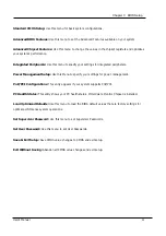
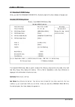
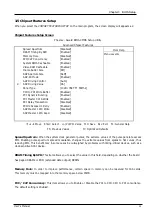
3.2 CMOS Setup Utility
To access the AWARD BIOS SETUP program, press the <DEL> key. The screen display will appears as
shown below:
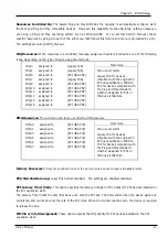
Main Program Screen
Phoenix - Award BIOS CMOS Setup Utility
f
Standard CMOS Features
f
PC Health Status
f
Advanced BIOS Features
Load Optimized Defaults
f
Advanced Chipset Features
Set Supervisor Password
f
Integrated Peripherals
Set User Password
f
Power Management Setup
Save & Exit Setup
f
PnP/PCI Configurations
Exit Without Saving
Esc :
Quit
Ç
È
Æ
: Select Item
F10
: Save & Exit Setup
Time, Date, Hard Disk Type...
This screen provides access to the utility‘s various functions.
Listed below is explanation of the keys displayed at the bottom of the screen:
<ESC>: Exit the utility.
<
Ç
Ç
Ç
Ç
È
È
È
È
Æ
Æ
Æ
Æ
Å
Å
Å
Å
>: Use arrow keys
Ç
È
Æ
Å
to move cursor to your desired selection.
<F1> : General Help
<F10>: Saves all changes made to Setup and exits program.
Содержание EM-568 Series
Страница 4: ......
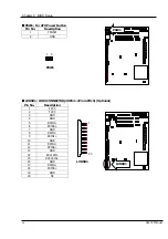
Страница 8: ...Chapter 1 Introduction 4 User s Manual 1 5 Board Layout...