Lanier R/C MARINER 40 MK II ARF Скачать руководство пользователя страница 17

17

❏ 

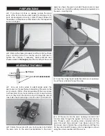
4. Remove the cowl from the fuse. A rotary tool is 

recommended for cutting the cowl for the engine head. Make 
any other necessary cutouts in the cowl such as access 
for the needle valve. Replace the engine on the fi rewall (or 
cylinder head).

❏ 

5. Return the cowl to the fi rewall and tape it in place again 

being sure to align the front of the cowl with the spinner 
backplate. The cowl should be spaced 3/32" [2.4mm] behind 
the backplate. Drill 1/16" [1.6mm] holes through the cowl and 
into the three cowl mounting blocks. Drill two additional holes 
near the bottom of the cowl on both sides 1/4" [6mm] from 
the aft edge of the cowl. Remove the cowl once more and 
thread a #2 x 3/8" [9.5mm] screw into each hole and back it 

out. Apply a drop of thin CA to each hole. Enlarge the holes 
in the cowl with a 3/32" [2.4mm] drill bit. Mount the cowl 
using fi ve #2 x 3/8" [9.5mm] screws and fi ve #2 fl at washers.

❏ 

6. Trim the covering from the canopy hatch screw holes 

in the fuselage. Fit the canopy hatch to the fuselage and 

secure it using two 2-56 x 3/4" [19mm] machine screws and 
two #2 fl at washers.

❏ 

7. Install the spinner back plate, propeller, prop washer 

and nut onto the engine crankshaft. Test fi t the spinner cone 
onto the backplate. Enlarge the blade slots in the spinner 
cone if necessary using a rotary tool or hobby knife. Be sure 
that the prop blades do not touch the spinner cone. When 
satisfi ed, install the spinner cone onto the backplate using 
the included spinner screws.

❏ 

8. That completes the assembly of the Stinger II .46 ARF! 
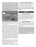
Apply the Decals

1. Use scissors or a sharp hobby knife to cut the decals from 

the sheet. 

2. Be certain the model is clean and free from oily fi ngerprints 
and dust. Prepare a dishpan or small bucket with a mixture 
of liquid dish soap and warm water—about one teaspoon of 
soap per gallon of water. Submerse the decal in the soap and 
water and peel off the paper backing. 

Note:

 Even though the 

decals have a “sticky-back” and are not the water transfer 
type, submersing them in soap & water allows accurate 
positioning and reduces air bubbles underneath. 

3. Position decal on the model where desired. Holding the 
decal down, use a paper towel to wipe most of the water 
away.

4. Use a piece of soft balsa or something similar to squeegee 

remaining water from under the decal. Apply the rest of the 
decals the same way. 

Содержание MARINER 40 MK II ARF

Страница 1: ... product By the act of using the user assembled product the user accepts all resulting liability If the buyer is not prepared to accept the liability associated with the use of this product the buyer is advised to return this kit immediately in new and unused condition to the place of purchase To make a warranty claim send the defective part or item to Hobby Services at the address below Hobby Ser...

Страница 2: ...there is new technical information or changes to this model a tech notice box will appear in the upper left corner of the page AMA Academy of Model Aeronautics If you are not already a member of the AMA please join The AMA is the governing body of model aviation and membership provides liability insurance coverage protects modelers rights and interests and is required to fly at most R C sites Acad...

Страница 3: ...tion two 6 152mm servo extensions are required for the aileron servos If you are using a radio system that does not support mixing functions a Y harness will also be required to connect the aileron servos to the receiver Recommended part numbers for the radio components are provided below 5 Futaba S3004 Standard Ball Bearing Servo FUTM0004 2 Hobbico 6 Extension Futaba J HCAM2000 Futaba Dual Servo ...

Страница 4: ...Photos and sketches are placed before the step they refer to Frequently you can study photos in following steps to get another view of the same parts The stabilizer and wing incidences and engine thrust angles have been factory built into this model However some technically minded modelers may wish to check these measurements anyway To view this information visit the web site at greatplanes com an...

Страница 5: ...MA4238 GPMA4239 Wing Fuselage Tail Surface Set Hatch Cowl Landing Gear Wheel Pants Spinner Wing Tube Decals REPLACEMENT PARTS LIST KIT INSPECTION Before starting to build take an inventory of this kit to make sure it is complete and inspect the parts to make sure they are of acceptable quality If any parts are missing or are not of acceptable quality or if you need assistance with assembly contact...

Страница 6: ...o cases Cut three arms from a four armed servo arm for each aileron servo so they match the photo in step 2 Enlarge the second inner hole of each remaining arm with a 5 64 2mm drill bit 2 Center the servos with your radio system and install the servo arms to the servos perpendicular to the servo cases as shown Be sure to reinstall the servo arm screws into the servos Install the rubber grommets an...

Страница 7: ... control horns onto the ailerons using 2 56 x 5 8 16mm machine screws and control horn backplates 8 With the ailerons in the neutral position use tape or small clamps to hold them in place and the servos centered mark the pushrod wires where they cross the second inner holes in the servo arms Servo Horn 1 16 2 56 074 Pushrod Wire FasLink 9 Make a 90 bend at the mark on each pushrod and cut off the...

Страница 8: ... wing tube into the fuselage and center it left and right 2 Fit the wings onto the wing tube The aileron servo leads should pass through the cutouts in the fuse sides and the anti rotation pins fit into their mating holes in the fuse Use the included nylon wing bolts to tighten the wings to the fuselage 3 Test fit the horizontal stabilizer into the stab slot in the fuselage 4 Insert the vertical f...

Страница 9: ... to view the model from behind Add weight to one side of the stab if necessary to bring it parallel with the wing and use tape to pull the fin square with the stab if necessary When satisfied let the epoxy completely cure undisturbed 7 You can now remove the wing panels and set them aside DRILL A 5 64 2mm HOLE 3 8 9 5mm DEEP IN CENTER OF HINGE SLOT CUT THE COVERING AWAY FROM THE SLOT 8 Prepare the...

Страница 10: ...ied apply 6 drops of thin CA glue to the center of each hinge on both sides the hinges will hold the rudder in place while the epoxy on the tail wheel wire and tab hardens When the CA has dried gently pull on the rudder to confirm that it is securely glued in place INSTALL THE TAIL PUSHRODS AND SERVOS 1 Thread a nylon clevis onto each of the 27 686mm pushrods along with silicone clevis retainers A...

Страница 11: ...the servo arms referenced in the previous step 5 Make 90 bends at your marks and cut off the excess pushrod 1 4 6mm beyond the bends Connect the pushrods to the tail servos using nylon FasLinks ASSEMBLE AND INSTALL THE LANDING GEAR 1 Install an axle into each main landing gear leg and tightly secure them using 7 32 28 nuts 2 Slide a plastic spacer followed by a wheel and then a 5 32 4mm wheel coll...

Страница 12: ...es should extend out 1 2 13mm beyond the stopper and the vent line should be bent upwards and left uncut With the tubes installed in the stopper fit the stopper plates loosely in place with the 3 x 25mm phillips screw to hold the assembly together 2 Fit the stopper assembly into the tank with the vent line pointing toward the top of the tank but not touching The fuel tubing and clunks fuel pickup ...

Страница 13: ... 6 32 x 1 25mm machine screws four 6 flat washers four 6 lock washers and thread locking compound Leave the screws slightly loose Test fit your engine between the mount halves Slide the mount halves against the sides of the engine and finish tightening the mount screws 7 Position the front of the engine drive washer 4 1 2 114mm from the front of the firewall Mark the location of the engine mount h...

Страница 14: ...lock pushrod connector into the outer hole in the remaining arm and secure it in place with a nylon screw lock connector retainer Loosely install a 4 40 set screw into the screw lock pushrod connector Install the throttle servo onto the throttle servo tray using the hardware supplied with the servo 11 Drill a 3 16 4 8mm hole in the firewall inline with the throttle arm on the carburetor An extra l...

Страница 15: ...e location shown Thoroughly glue the clip in place Apply some CA glue where the outer pushrod tube passes through the firewall FINISH THE MODEL Install the Receiver and Battery 1 Wrap your receiver and receiver battery pack in foam rubber Make a strap from the remainder of the included hook and loop material to fit both of the components when stacked Strap the receiver and pack to the tray as show...

Страница 16: ... should be approximately 1 4 6mm larger on all sides than the engine head Tape the template to the fuselage side so the cutout in the template is aligned over the engine head 3 In order to fit the cowl onto the fuselage the engine will need to be temporarily removed from the firewall so the head does not interfere Just the cylinder head can also be temporarily removed if you are comfortable doing ...

Страница 17: ...flat washers 7 Install the spinner back plate propeller prop washer and nut onto the engine crankshaft Test fit the spinner cone onto the backplate Enlarge the blade slots in the spinner cone if necessary using a rotary tool or hobby knife Be sure that the prop blades do not touch the spinner cone When satisfied install the spinner cone onto the backplate using the included spinner screws 8 That c...

Страница 18: ...2 5 8 67mm 31 Left 1 25mm 11 Right 1 25mm 11 Left AILERONS 15 16 24mm 15 Up 15 16 24mm 15 Down 5 8 16mm 10 Up 5 8 16mm 10 Down IMPORTANT The Stinger has been extensively flown and tested to arrive at the throws at which it flies best Flying your model at these throws will provide you with the greatest chance for successful first flights If after you have become accustomed to the way the Stinger fl...

Страница 19: ... bottom of the fuse and gluing it permanently inside Note Do not rely upon the adhesive on the back of the lead weight to permanently hold it in place Over time fuel and exhaust residue may soften the adhesive and cause the weight to fall off Use 2 sheet metal screws RTV silicone or epoxy to permanently hold the weight in place 4 IMPORTANT If you found it necessary to add any weight recheck the C ...

Страница 20: ...parks or flames as fuel is very flammable Do not smoke near the engine or fuel and remember that engine exhaust gives off a great deal of deadly carbon monoxide Therefore do not run the engine in a closed room or garage Get help from an experienced pilot when learning to operate engines Use safety glasses when starting or running engines Do not run the engine in an area of loose gravel or sand the...

Страница 21: ...tant areas are not overlooked Many are covered in the instruction manual so where appropriate refer to the manual for complete instructions Be sure to check the items off as they are completed 1 Check the C G according to the measurements provided in the manual 2 Be certain the battery and receiver are securely mounted in the fuse Simply stuffing them into place with foam rubber is not sufficient ...

Страница 22: ...r to keep the tail wheel on the ground If necessary adjust the tail wheel so the model will roll straight down the runway If you need to calm your nerves before the maiden flight shut the engine down and bring the model back into the pits Top off the fuel then check all fasteners and control linkages for peace of mind Remember to takeoff into the wind When you re ready point the model straight dow...

Страница 23: ...y and has lost flying speed hold up elevator to place the tail on the ground regaining tail wheel control One final note about flying your model Have a goal or flight plan in mind for every flight This can be learning a new maneuver s improving a maneuver s you already know or learning how the model behaves in certain conditions such as on high or low rates This is not necessarily to improve your ...

Страница 24: ......

Отзывы: