background image

2020.04.23 P1202 P1301 user manual PS LG GM Final.docx 


User Manual 


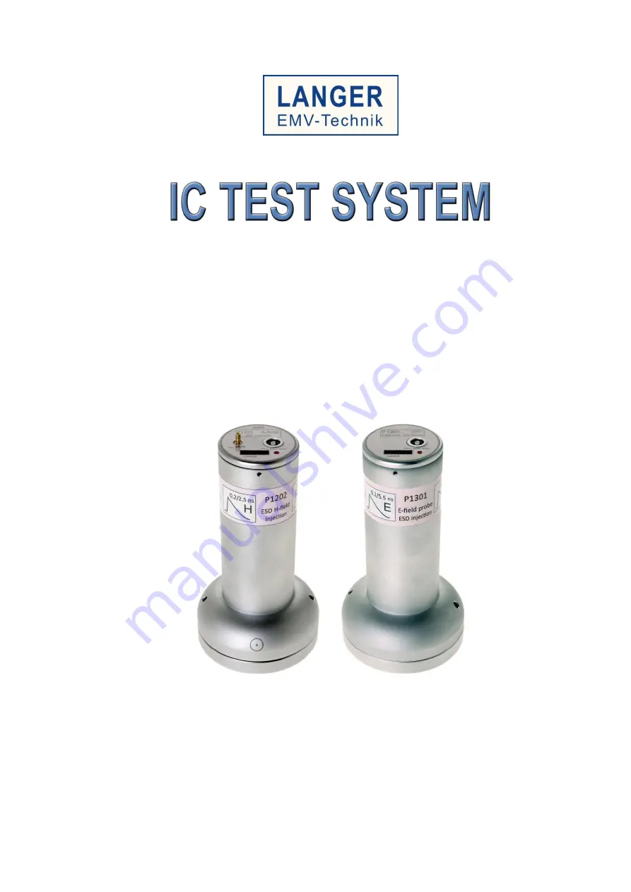
P1202 / P1301 L-ESD set 

ESD Langer Pulse H 0.2/2.5 E 0.2/5.5 ns Field Coupling


IC immunity test against ESD electric and magnetic field 


- Translation of the original user manual - 

Copyright © Februar 2020 
LANGER EMV-Technik GmbH


Содержание P1202

Страница 1: ...Final docx User Manual P1202 P1301 L ESD set ESD Langer Pulse H 0 2 2 5 E 0 2 5 5 ns Field Coupling IC immunity test against ESD electric and magnetic field Translation of the original user manual Cop...

Страница 2: ...Shunt 8 4 3 P1301 L ESD General Parameters 9 4 4 P1301 L ESD Electric Field Strength 9 4 5 BPM 02 dB dt Field Meter 10 4 6 EPM 02 dE dt Field Meter 10 4 7 BPS 203 Burst Power Station 10 4 8 Intended U...

Страница 3: ...ly P1202 27 8 4 Calibration of the Measurement Set up 29 8 5 Measurement Sequence 30 8 6 BPS 203 Client Software 31 9 Installation 31 9 1 Software Client General Notes 31 9 2 Pulse Configuration 32 9...

Страница 4: ...ame Designation P1202 P1301 L ESD set mit with avec BPS 203 P1202 P1301 EPM 02 BPM 02 mit den folgenden Bestimmungen with applicable regulations avec les directives suivantes EMV Richtlinien EMV Direc...

Страница 5: ...ume no liability for damage to property and personal injury if The information given in this user manual has not been observed P1202 P1301 L ESD set was operated by staff not qualified in the field of...

Страница 6: ...8 Bannewitz mail langer emv de www langer emv com P1202 P1301 L ESD set Description of Symbols 2 8 Warning signs Prohibition Signs General warning sign No access for people with active implanted cardi...

Страница 7: ...ient 1 5 dB dt Field Meter BPM 02 1 6 dE dt Field Meter EPM 02 1 7 Spacer Ring 3 mm D70 h03 1 8 Spacer Ring 10 mm D70 h10 1 9 Field Chamber Insert FKE 30 1 10 Measuring Cable SMA SMB 1 m 2 11 High Vol...

Страница 8: ...202 L ESD Magnetic Flux Density B 4 2 in kV 0 5 1 1 5 2 2 5 3 3 5 4 4 5 5 5 5 6 Viout in V 0 6 1 2 1 8 2 4 3 3 6 4 2 4 8 5 4 6 6 6 7 2 P in A 12 24 36 48 60 72 84 96 108 120 132 144 D70 h03 spacer hei...

Страница 9: ...ns Frequency 0 1 Hz 10 Hz Voltage 0 1 6 kV Connector input 50 Fischer D103A023 Table 4 P1301 general parameters P1301 L ESD Electric Field Strength 4 5 in kV 0 5 1 1 5 2 2 5 3 3 5 4 4 5 5 5 5 6 D70 h0...

Страница 10: ...Table 6 Conversion factor of BPM 02 EPM 02 dE dt Field Meter 4 7 Frequency range 500 kHz 3 GHz Electric field strength calculation based on the voltage uout at the measurement output E K uout K 251 d...

Страница 11: ...s such as test the immunity of integrated circuits ICs against magnetic and electric fields determine the orientation of critical loops within the tested IC The user must comply with all information a...

Страница 12: ...bnormal use are excluded Safety Instructions 5 3 General Safety Information 5 3 1 Risks cannot be totally excluded even if the P1202 P1301 L ESD set is used for its intended purpose Observe the safety...

Страница 13: ...or electric components Hazard due to Electromagnetic Fields Near and Far Fields 5 3 3 Danger from electromagnetic fields Risk of affecting a cardiac device Persons with a cardiac device such as a pace...

Страница 14: ...nnecting a protective resistor in the test IC s incoming power supply increasing the intensity gradually and stopping when a functional fault occurs or interrupting the power supply to the test IC in...

Страница 15: ...ls HV signal cable Connects L ESD field sources with the BPS 203 Measurement cable SSMB to SMA cable to connect measurement output with an oscilloscope D70 h03 Spacer ring with height of 3 mm D70 h10...

Страница 16: ...t for the L ESD field sources The BPS 203 is connected to a computer with windows operating system The provided installation medium includes the BPS 203 Client software and a DLL for implementing auto...

Страница 17: ...to a PC Table 9 BPS 203 features LED State Description Status 10Hz Fault Probe is not connected or is incorrectly connected 2Hz Probe is ready both cables have to be connected 2Hz Pulse operation HV r...

Страница 18: ...e high voltage input is marked HVin and the measurement output is marked iout Figure 6 P1202 ESD field source with 3 cm long electric conductor On the inside of the P1202 ESD field source see Figure 3...

Страница 19: ...ource the spacer ring the field chamber insert and the ground plane with the test IC form a field chamber This field chamber limits and shields the generated magnetic field A shunt is located in the c...

Страница 20: ...th the P1202 field source and the D70 h10 spacer ring The field chamber insert has to be installed at the bottom of the P1202 field source as shown in Figure 8 The field chamber insert ensures a highe...

Страница 21: ...source On the inside of the P1301 ESD field source see Figure 10 the HV power input is connected to the pulse shaping circuit The output of the pulse shaping circuit is connected to the electrode loca...

Страница 22: ...can be measured with the BPM 02 and EPM 02 field meters respectively To do so a field meter has to be inserted in the GND 25 ground plane2 using the GNDA 02 ground adapter3 To calculate the magnetic f...

Страница 23: ...ld sources above the test IC while providing a ground connection between the hull of the field source and ground system of the test IC The height of the spacer ring determines the distance between the...

Страница 24: ...ith an asterisk The following components not included in the scope of delivery are also needed ICE1 set IC test environment Langer EMV Technik GmbH Measuring and test devices e g Oscilloscope Test boa...

Страница 25: ...These are visible in Figure 6 and can be used to adjust the orientation of the field source on the spacer ring The electric conductor and the magnetic field are perpendicular to each other in the area...

Страница 26: ...n Provision of connections for devices such as an oscilloscope to monitor the operation condition and or detect faults For further information on manufacturing the test board please refer to IEC 62132...

Страница 27: ...tings for the oscilloscope resulting from the shunt external attenuator and 50 termination are found in Table 11 To get a proper pulse current reading the damping factor in the oscilloscope must be se...

Страница 28: ...17 5 120 6 1 88 0 6 0 19 5 5 132 6 6 2 06 0 66 0 21 6 144 7 2 2 25 0 72 0 23 Table 12 Input voltage present at oscilloscope using different attenuators The P1202 field source s measurement output can...

Страница 29: ...voltage HVin see Table 2 and Table 5 The values of the generated field strength have to be stored in the BPS 203 client for each high voltage step After the calibration the field meters are removed an...

Страница 30: ...witz mail langer emv de www langer emv com P1202 P1301 L ESD set Measurement Sequence 8 6 The basic measurement can be carried out in accordance with IEC 62132 2 2010 for example Figure 20 Flow chart...

Страница 31: ...the device driver installation which follows automatically Software Client General Notes 9 2 The BPS 203 Client software contains the control elements needed to operate the BPS 203 and its probes in i...

Страница 32: ...When enabled the BPS 203 issues only the predefined number of pulses After all pulses are issued the BPS 203 returns to the wait state Figure 24 Impulse counter Probe Parameter Read Out 9 5 Depending...

Страница 33: ...ulse parameters Additionally the LED on the field source and the Status LED on the BPS 203 will blink continuously The software s status will display Status running and the Start Pulsing button is ren...

Страница 34: ...r Trigger BPS 203 waits for an external trigger event Figure 29 No USB connection to BPS 203 Figure 30 BPS 203 connected but no valid probe detected Figure 31 BPS 203 connected and the P1202 field sou...

Страница 35: ...will be forfeited if an unauthorized repair is performed on the product the product is modified the product is not used for its intended purpose the product has been opened This document may not be co...

Отзывы: