2
A spirit level, placed on an oven rack, will assist
in leveling the oven.
STACKING THE OVENS
Remove all of the
plug buttons
from the top of
the
lower oven
.
Remove the
stacking kit
from the oven
compartment.
Tip the
top oven
backwards and install two 3/8
diameter Allen Head bolts (found in the stacking
kit) into the two front leg holes that match the
holes in the top of the lower oven. Install the
Allen Head bolts with the heads of the bolts
pointing away from the oven.
Lift the top oven and gently set on top of the
lower so that the heads of the bolts nest into the
holes in the top of the lower oven.
FLU EXTENSION
A flu extension must be installed on the lower
oven of a stacked set. The extension attaches to
the flu opening of the lower oven and directs the
flu products into the flu opening of the upper
oven.
This extension must be installed.
The ovens may now be set into position. Be
careful if sliding the ovens, they are not designed
to slide over cracks or obstructions in the floor.
GAS CONNECTION
DANGER
AS WITH ANY GAS APPLIANCE INSTALLED ON CASTERS,
ANY LANG GAS GRIDDLE, GAS CLAMSHELL
®
, OR GAS
CONVECTION OVEN ON CASTERS MUST BE INSTALLED
WITH THE FOLLOWING:
A CONNECTOR THAT COMPLIES WITH THE STANDARD
FOR CONNECTORS FOR MOVABLE GAS APPLIANCES,
ANSI Z21.69 LATEST EDITION.
AND
A QUICK DISCONNECT THAT COMPLIES WITH THE
STANDARD FOR QUICK DISCONNECT DEVICES FOR USE
WITH GAS FUEL, ANSI Z21.41 LATEST EDITION.
AND
A TETHER OR OTHER MEANS TO LIMIT APPLIANCE
MOVEMENT WITHOUT RELIANCE ON THE GAS SUPPLY
PIPING. SECURELY ATTACH THE TETHER TO THE
EYEBOLT PROVIDED AT THE REAR OF THE APPLIANCE.
FAILURE TO INSTALL THESE PARTS CAN LEAD TO
LEAKAGE OF GAS AND RESULTING FIRE, EXPLOSION,
PERSONAL INJURY AND DEATH.
This appliance is manufactured for use with the
type of gas indicated on the data plate. Contact
the factory if the gas type does not match that
which is on the data plate.
All gas connections must be in accordance with
local codes and comply with the National Fuel
Gas Code ANSI Z223.1 latest edition.
A internal gas pressure regulator is located
inside the control compartment.
Gas must be delivered to the appliance regulator
at less than 1/2 pound of pressure and less than
1/2 inch water column pressure drop.
The internal regulator is preset at the factory,
however, due to gas pressure variations from
area to area, adjust the regulator to provide the
manifold pressure indicated on the data plate.
This should be 5 inches water column for natural
gas and 10 inch water column for propane. A
1/8 inch NPT tap is provided on the main
manifold for checking regulator pressure.
Access the main manifold by removing the trim
piece below the oven doors.
When replacing the 1/8 inch plug in the main
manifold a joint sealant that is resistant to the
action of liquid petroleum gas must be used.
The supply piping must be of sufficient size to
provide 55,000 BTU/hr per oven. A 1/2 inch
NPT connection is provided at the rear of the
oven directly behind the control compartment.
Connect each oven separately.
A gas shut off valve must be installed to the
oven(s) and located in an accessible area.
This appliance and its individual shutoff valve
must be disconnected from the gas supply piping
system during any pressure testing of that system
at test pressures in excess of 1/2 PSGI (3.45
kPA) and the appliance must be isolated from
the gas supply piping system by closing its
individual manual shutoff valve during any
pressure testing of the gas supply system at test
pressures equal to or less than 1/2 PSIG (3.45
kPA).
Test for gas leaks. Use a commercial leak
detector or a soap and water solution.
WARNING
DO NOT USE AN OPEN FLAME TO TEST
FOR GAS LEAKS.
ELECTRICAL CONNECTION
WARNING
ELECTRICAL GROUNDING
INSTRUCTIONS
Содержание GCCO-C
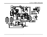
Страница 16: ...13 GCCO C WIRING DIAGRAM...


