E1/G.703 F
IBER
O
PTIC
M
ODEM
O
PERATING
M
ANUAL
IOA76-1F
17
May 2009
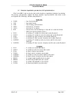
Table 7.
TM-76 - computer connecting cable specification
TM-76.1 modem side
PC computer or terminal side
RJ-45 connector
Pin symbol
DSUB-9 female
connector
DSUB-25 female
connector
6
Tx 2
3
5
Rx 3
2
RTS – CTS
7 – 8
4 – 5
DTR - DSR
4 – 6
6 – 20
4
SGND 5
7
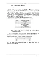
MD-76 and MD-77 cards in TM-72 rack can be managed with the
Lanwin
software
installed on a PC computer. TM-72 rack must be equipped with MD-91 management card.
The managing computer should be connected to the rack with the cable specified in the table
below.
Table 8.
TM-72 - computer connecting cable specification.
TM-72 rack MD-91 card
side
PC computer or terminal side
DSUB-9 connector
(female)
Pin symbol
DSUB-9 female
connector
DSUB-25 female
connector
2
Tx 2
3
3
Rx 3
2
RTS – CTS
7 – 8
4 – 5
DTR - DSR
4 – 6
6 – 20
4
SGND 5
7
casing
casing casing
4.6 Fiber optic line connection
The maximum length of a fiber optic line to connect devices is not a unequivocal value
because it depends on external factors, such as light pipe attenuation coefficient, through-
connector attenuation as well as the accepted safety margin. The length, i.e. range can be
determined by performing an optical power balance.
The power balance for the devices is shown in 09. The fiber optic line length calculated in
the are maximum values for the adopted assumptions (maximum values from the cable catalog
of the Optical Telecommunications Technology Center in Lublin are used as light pipe
attenuation coefficients). When other assumption are used, the obtained values can be slightly
different.
Содержание MD-76
Страница 42: ...E1 G 703 FIBER OPTIC MODEM OPERATING MANUAL IOA76 1F 36 May 2009 Figure 27 G 826 statistics...
Страница 54: ......
Страница 55: ......


