background image


Retrofit kit for dial indicator test devices  

ed. 01/2017 

page 8 

6


Assembly and set-up 

This chapter shall help you to answer any questions which might arise before or during the assembly and 
set-up of the retrofit kit. Please go through the described steps one after the other. 

6.1 

Assembly of the base unit 

When choosing the position of the test station, the ambient conditions required by the manufacturer of 
the dial indicator test device have to be observed. 

The base unit has to be placed upon a stable structure which is free from vibrations and is sufficiently able 
to take load (weight of the base unit plus weight of the dial indicator testing device). When choosing the 
position  for  the  test  station,  you  should  also  consider  the  necessary  space  for  computer  equipment 
(keyboard,  mouse,  screen).  Please  also  pay  attention  to  the  glare  effect  of  the  lighting  unit  –  we 
recommend to place the testing station facing a wall, or to install an optical screen between adjacent work 
stations, e.g. by means of a vertical partition. 

Take the base unit out of the transport packaging. Please remove the foam inserts very carefully to avoid 
any deformation or damage of the pre-assembled camera and lighting unit. 


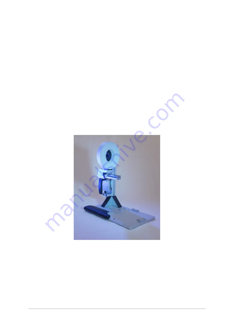
Fig.2: base unit with pre-assembled camera with lens and lighting unit  

Place the base unit on the chosen workplace. The column with the camera and lighting unit should be on 
the front side close to the operator. 


Содержание QMSOFT retrofit ki

Страница 1: ...QMSOFT Retrofit kit for fully automated testing with dial indicator test devices 2016 2017 L W GmbH ...

Страница 2: ...tor test devices ed 01 2017 page 2 Trademarks used in this document Microsoft Windows registered trademark of Microsoft Corporation Redmond QMSOFT registered trademark of L W GmbH CodeMeter registered trademark of WIBU SYSTEMS AG ...

Страница 3: ... 6 1 CREATE THE TEST DEVICE IN THE QMSOFT QM DEVICESERVER 16 6 6 2 CONFIGURATION OF THE TEST DEVICE IN THE QMSOFT QM DEVICESERVER 17 6 6 3 CONFIGURATION OF THE INSPECTION PROGRAM QMSOFT QM DIAL 19 7 IMAGE PROCESSING IN QMSOFT QM DIAL 21 7 1 USER INTERFACE OF THE QMSOFT CAMERA FUNCTIONS 21 7 1 1 MOTION CONTROL OF THE DIAL INDICATOR TEST DEVICE 22 7 1 2 SETTINGS FOR THE CAMERA IMAGE 22 7 2 INSPECTIO...

Страница 4: ...ctronic license extension The CmStick contains a single license for QMSOFT QM DIAL image processing or in case of an already existing QMSOFT QM DIAL license the license extension QMSOFT QM DIAL bv extension for image processing When the retrofit kit is delivered together with other QMSOFT software components the QMSOFT installation set DVD and CmStick might be delivered in a separate package NOTE ...

Страница 5: ...designed to hold the retrofit kit together with a mounted dial indicator test device The transport box has the following dimensions slight deviations due to technical development are possible Length 57 8 cm Width 39 5 cm Height 62 5 cm The entire delivery unit has a weight of approx 16 kg NOTE At delivery please check the transport packaging for any shipping damage which might have damaged the del...

Страница 6: ... connecting the power supply of the lighting unit please check if the supply voltage indicated on the type plate of the plug in power supply corresponds with the local voltage Should they not correspond do not connect the power supply Always disconnect the power supply of the lighting unit before starting any maintenance works on the lighting unit Assembly works on the retrofit kit must only be ca...

Страница 7: ...inter or numeric display of the test object and the reference measuring values of the dial indicator test device it also performs all the subsequent processes related to gauge management The license QMSOFT QM DIAL image processing for new customers or QMSOFT QM DIAL bv for QMSOFT customers already possessing a compatible QMSOFT QM DIAL license contains the software functions to allow the reading o...

Страница 8: ...unit plus weight of the dial indicator testing device When choosing the position for the test station you should also consider the necessary space for computer equipment keyboard mouse screen Please also pay attention to the glare effect of the lighting unit we recommend to place the testing station facing a wall or to install an optical screen between adjacent work stations e g by means of a vert...

Страница 9: ... for horizontal positioning of the slide with the lighting unit 5 slide with lighting unit horizontally adjustable 6 camera lighting unit slide vertically adjustable 7 clamp for vertical positioning of the camera lighting unit 8 handle for horizontal positioning of the camera lighting unit 9 hand wheel for manual testing with the Optimar device 10 testing device dial gauge test device Optimar not ...

Страница 10: ...lt and four adjustable stops in the form of aluminum blocks with fixing screws which can be fitted within a limited range to the socket of the dial gauge test devices Fig 4 Assembly scheme top view First unfasten the fixing screws of the rear and left stop marked with red darts in the figures and remove them Fig 5 stops to be unfastened ...

Страница 11: ...e of the test instrument fits well in between the stops on the front and on the right side of the base plate Now replace the unfastened stops and fix the position of the dial indicator test device by fitting the stops tightly to the socket of the test device and re fasten the fixing screws Fig 6 front stops To position the lighting unit see Fig 7 loosen the clamp 1 of the horizontal slide of the l...

Страница 12: ...d of the handle 5 with your right hand and loosen the clamp 3 with your left hand Now you can move the slide in vertical direction finding a position where camera lighting unit and the dial gauge to be tested are all in line Fix the slide in this position by tightening the clamp 3 ATTENTION Do not let go of the handle while the clamp is unfastened to avoid the risk of a collision of the slide with...

Страница 13: ...nents are updated and all the necessary Windows updates are installed correctly Only then continue with the set up Now start the dial indicator test device and carry out all the operating steps for starting the testing device required by the manufacturer to put it in operating condition 6 4 Set up of the lighting unit ATTENTION Before setting up the lighting unit always check that the supply volta...

Страница 14: ... you can find the program file uEye64_46000_WHQL exe Double click to start the file select install driver and follow the instructions we recommend the setup type complete for the installation of the driver Take over the default settings for the target directory and for the program folder To finalize the installation process you may choose to install the shortcut icons for the camera software also ...

Страница 15: ...indow of the camera software You should now be seeing a black and white real time image on your screen do not forget to remove the protective cap from the lens of the camera Depending on the position of the lens the brightness of the computer image might be too high or too low in this case you can correct the brightness by adjusting the lens aperture on the camera see Fig 8 You can vary the zoom f...

Страница 16: ...Optimar 100 please carry out the following steps 6 6 1 Create the test device in the QMSOFT QM DeviceServer Before you can start using the dial indicator test device in the QMSOFT system the device has to be created in the QMSOFT QM DeviceServer Open the main window QMSOFT GaugeMan and click on the first button in the section Measuring devices Fig 12 starting of the QMSOFT QM DeviceServer Now the ...

Страница 17: ...ocess with the Close button The dial indicator test device has now been created in the QMSOFT QM DeviceServer 6 6 2 Configuration of the test device in the QMSOFT QM DeviceServer Select the testing device in the program window By clicking on the right mouse button you open a menu where you choose the function modify device properties Fig 15 menu Modify device properties ...

Страница 18: ...e and to select the USB camera to be used for reading the measured values on the display of the test object see Fig 16 Fig 16 Modify device properties The default settings for the axis designations shown in the window can remain unchanged Further settings are not required and you can confirm the configuration with OK In the main window of the QMSOFT QM DeviceServer you now click on the button ...

Страница 19: ...e test device you created Start by clicking on the QM DIAL symbol indicated by the red dart in Fig 17 Fig 17 Starting the dial gauge inspection program QMSOFT QM DIAL Open the menu Settings Program settings where you select program settings Fig 18 Select the device connection to the dial gauge test device and confirm with OK Fig 18 Configuration of the connection to the test device You may choose ...

Страница 20: ...mend to pre set the inspection mode on fully automated inspection see Fig 19 Fig 19 Activation of fully automated inspection QMSOFT recognizes automatically whether the connected test device is linked to a camera No further settings are necessary For detailed information on the functions and configuration options in QMSOFT please refer to the QMSOFT manual ...

Страница 21: ...a function With respect to conventional devices you will find new control elements here which are shortly described on the following pages Fig 20 test device visualization Optimar 100 To facilitate the positioning of the camera you can add the red line as shown in Fig 20 by selecting mark elements on the right of the image Bring the red line into alignment with the center of the test object s scal...

Страница 22: ...stop in case the movement of the quill has to be interrupted quickly e g to avoid collision 7 1 2 Settings for the camera image Button One click on this button activates the camera image which automatically enlarges the test device visualization In the automatic mode the camera image starts without intervention of the operator With this function the reading via camera can be activated also during ...

Страница 23: ...ested dial gauge 7 2 2 1 Analogue dial gauges Position the quill of the dial indicator test device so that the test object is in a position shortly before its mechanical pointer s zero point and make sure there is a contact between the quill of the test device and the test object A symbol in the top left corner of the camera image shows the expected position of the 0 top bottom left or right By cl...

Страница 24: ...testing by clicking on the button Start fully automated inspection in the QMSOFT QM DIAL program window The software now first starts trying to recognize the scale of the test object or to evaluate the numeric display In doing this the test object is being moved slightly by the movement of the quill of the test device After this short recognition process starts the inspection of the test object in...

Страница 25: ...e retrofit kit has been designed to allow a virtually maintenance free operation under normal laboratory conditions From time to time remove any dust deposits on the components especially on the camera Pay attention to possible dirt deposits on the guide elements of the positioning slides ...

Страница 26: ...rol in QMSOFT The camera image flickers Increase the brightness exposure time in QMSOFT and decrease the brightness on the lens of the camera QMSOFT QM DIAL does not show the test device visualization Has the connection between QM DIAL and QMSOFT QM DeviceServer been configured Is the QMSOFT QM DeviceServer active Can the test device be called up in the QMSOFT QM DeviceServer Are the settings for ...

Отзывы: