background image

Page A - 53 

A


LW 100 Series 
Version: 29.03.2016 

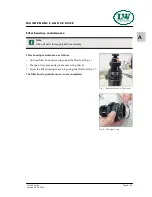
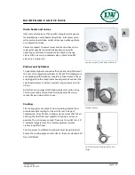
Fig. 1 - Remove/screw in filter cover 

M A I N T E N A N C E   A N D   S E R V I C E  

Filter housing - maintenance 


Filter housing maintenance as follows: 

•  Unscrew filter housing cover by using the filter tool (Fig. 1). 

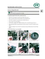
•  Change o-ring, previously grease new o-ring (Fig. 2) 

•  Screw the filter housing cover in by using the filter tool (Fig. 1). 

The filter housing maintenance is now completed. 

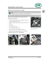
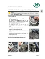
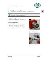
Fig. 2 - Change o-ring 

Note 

Clean all parts thoroughly before assembly. 

Содержание LW 100 B

Страница 1: ...ment A B C D Manufacturer in terms of 97 23 EC The full name and address of the manufacturer is Lenhardt Wagner GmbH An der Tuchbleiche 39 68623 Hüttenfeld Germany Phone 49 0 62 56 85 88 0 0 Fax 49 0 62 56 85 88 0 14 E Mail service lw compressors com Internet www lw compressors com Version 11 12 E ...

Страница 2: ...invoice Should verifiably defective parts have been delivered we will decide to either replace the parts or repair them The resulting transport and assembly costs will be invoiced No reduction of the purchase price or changes to the contract can be made The parts for which a claim is being made should be kept safe by the purchaser and when requested sent to us at their cost Replaced parts become t...

Страница 3: ...A Operating Instructions Breathing Air Compressor LW 100 series Version 29 03 2016 ...

Страница 4: ... Operators 13 Safety instructions on the unit 14 General Safety Precautions 15 Unit customised safety notices 16 Maintenance instructions 17 Transportation instructions Safety regulations 18 Installation Installation in closed rooms LW 100 E E1 20 Installation LW 100 B 21 Dimensions 22 Minimum distances 23 Ventilation LW 100 E E1 24 Electrical Installation LW 100 E E1 25 26 Operation Important ope...

Страница 5: ...r cartridge change 52 Filter housing maintenance 53 Inlet Filter 54 Check or change filter inlet 55 Valve heads and valves Pistons and Cylinders Cooling 56 Replace inlet and outlet valve 1st stage 57 58 Replace inlet and outlet valves 2nd and 3rd stage 59 Safety valves 60 Pressure maintaining non return valve 61 Adjust pressure maintaining valve 62 O rings filling valve and filling hose 63 Motor c...

Страница 6: ... these instructions is excluded from warranty and liability for this product Carry out other commissioning steps only if you have fully understood the following contents Before commissioning and using the unit carry out all the essential preliminary work and measures concerning legal regulations and safety These are described on the following pages of this operation manual G E N E R A L I N F O R ...

Страница 7: ... LW 100 E 2 2 kW E Motor 400V 230V 440V as an option 3 phase 50 Hz 60 Hz as an option Start Stop switch fully wired with cable and 16A CEE plug LW 100 E1 ECO LW 100 E1 2 2 kW E Motor 230 V AC 50 Hz as an option 60 Hz Start Stop switch fully wired with cable and two pin earthed plug 230V D E S C R I P T I O N LW 100 B ECO LW 100 B High performance Honda 4 gear motor 3 6 kW with integrated fuel tank...

Страница 8: ...r Motor protection switch Conversion set Petrol electro version 60 Hz Version 230V 440V Version LW 100 E E ECO only Power cable with plug Start Stop Switch Stainless steel frame aluminium frame ECO Manual condensate drain Pressure maintaining and non return valve 1 x Filling hose c w f lling valve and pressure gauge Intermediate coolers Oil Water separators after 2nd and 3rd stage Safety valves af...

Страница 9: ...unter Switch over device for 200 or 300 bar Conversion set Petrol electro version Stainless steel frame aluminium frame ECO Manual condensate drain Pressure maintaining and non return valve 1 x Filling hose c w f lling valve and pressure gauge Intermediate coolers Oil Water separators after 2nd and 3rd stage Safety valves after for each stage All pistons with piston rings Filling pressure to your ...

Страница 10: ...ed Air Breathing Air Intake Pressure atmospheric Oil Capacity l 0 5 0 5 0 5 Intake Temperature C 0 45 0 45 0 45 Ambient Temperature C 5 45 5 45 5 45 Cooling Air Volume m h 660 660 1350 Voltage Protection Class Drive Motor IP 55 IP 55 Drive Power kW 2 2 2 2 4 5 RPM Motor min 1 2890 2890 2890 Start Start Stop switch Hand start Noise level dB A 82 82 93 Dimensions L x W x H mm 650 x 390 x 400 650 x 3...

Страница 11: ...ion 29 03 2016 Unit Assembly LW 100 E E1 No Designation 1 Pressure gauge 2 Filling hose with filling valve 3 Carrying handles ECO Optional 4 E Motor 400V 3 Phase 50 Hz or E Motor 230V single phase 50Hz D E S C R I P T I O N 3 2 1 4 ...

Страница 12: ...sion 29 03 2016 No Designation 1 Pressure gauge 2 Intake telescopic pipe 3 Filling hose with filling valve 4 Carrying handles ECO Optional 5 4 stroke gasoline engine hand start D E S C R I P T I O N 4 3 1 5 2 Unit Assembly LW 100 B ...

Страница 13: ...ose 9 Condensate Release Valve 10 Oil Water Separator 11 3rd Pressure Stage 12 Endpressure Safety Valve 13 Cooling Pipe Final Stage 14 Condensate Release Hose 15 Condensate Release Valve 16 Oil Water Separator 17 Pressure Maintaining Valve 18 Non Return Valve 19 Filling Hose 20 Filling Connector 21 Filling Valve 22 Pressure Gauge Filling Pressure 23 Vent Valve 24 Unit Filling Valve Cross Design D ...

Страница 14: ...A S A F E T Y P R E C A U T I O N S ...

Страница 15: ... instruction manual is complied with and inspection and maintenance requirements are enforced No change and modification to the unit can be made without the written agreement of the manufacturer The manufacturer is not liable for damage to persons or property resulting from unauthorised modifications Operators Target groups in these instructions Operators Operators are persons who are authorized a...

Страница 16: ...Safety instructions on the unit Importance of notes and warning signs that are affixed to the compressor according to the application or its equipment S A F E T Y P R E C A U T I O N S Warning High voltage Note Ensure correct direction of rotation ...

Страница 17: ... and competent personnel are permitted to use this product Comply with all local and national rules and regulations associated with this product Only trained and competent personnel are permitted to inspect repair and service the product Only authentic L W parts and accessories may be used for maintenance work Otherwise the proper functioning of the product may be impaired Do not use faulty or inc...

Страница 18: ...under safe and functional conditions Only operate the compressor if all protective and safety equipment e g detachable protective equipment are provided and in good working order Check the compressor at least once per day for obvious damage and defects Inform the responsible department person immediately if anything is not as is should be including operation performance Shut down the machine immed...

Страница 19: ...especially the connections and fittings should be cleaned from oil fuel and maintenance products at the beginning of the maintenance repair Do not use aggressive cleaning agents Use fibre free cleaning cloths Switch off compressor and clean with a slightly damp cloth Remove dirt from cooling pipes by using a brush After cleaning examine all pipes for leaks loose connections chafing and damage Imme...

Страница 20: ...not stand or work under suspended loads Even minor relocation please disconnect the machine system from any external energy supply Before recommissioning reconnect the machine to the mains according to regulations When recommissioning proceed according to the operating instructions Safety regulations Inspections according to legal and local obligatory regulations regarding accident prevention are ...

Страница 21: ...A I N S TA L L AT I O N ...

Страница 22: ... the compressor fan can intake fresh air from outside Ensure adequate ventilation and exhaust air opening When locating the compressor in rooms of less than 30 m space where natural ventilation is not ensured or other systems having high radiation are operating in the same room measures must be taken to provide artificial ventilation Intake air must be free from noxious gas e g smoke solvent vapou...

Страница 23: ...sition compressor in direction of wind so that exhaust fumes are blown away from the unit Intake air must be free from noxious gas e g smoke solvent vapours exhaust fumes etc Observe the specified operating temperature see Technical Data Danger Compressors with petrol or diesel motors must only be located outdoors never indoors not even in partially closed rooms however large they may be Wind Wind...

Страница 24: ...Page A 22 A LW 100 Series Version 29 03 2016 Dimensions LW 100 E E1 400 650 390 Fig Dimensions 450 180 Dimensions LW 100 B 400 780 380 Fig Dimensions 450 180 I N S T A L L A T I O N ...

Страница 25: ...hered i Minimum distances Make sure that the compressor always has a sufficient amount of fresh air available To prevent serious damage ensure that the cooling air flow can flow freely The following minimum distances must be adhered Front side min 300 mm rear side min 300 mm Avoid anything in this area which can restrict the cooling air flow No minimum distances are required at the side panels ...

Страница 26: ...flow freely The necessary cooling air flow can be calculated by using the following formula 300 x drive power kW required cooling air flow m h Example 11kW motor 300 x 11kW 3300 m h required cooling air flow The fan capacity for fresh air and warm air must meet at least the required cooling air flow The fans must have the same capacity Fig Ventilation through facade Fig Ventilation via ventilation...

Страница 27: ...n and frequency with those of the electric network see name plate on the compressor The fusing should be done in accordance with the valid regulations of the responsible electricity supply company When connecting the unit to the electrical supply check the compressor direction of rotation see chapter Operation First commisioning LW 100 E E1 Fuse the motor correctly see table use slow blow fuses I ...

Страница 28: ...1 5 Electrical Installation LW 100 E E1 The compressor comes fully wired with cable and plug An installation is not necessary Recommended fuses for 220 240 V operating voltage Nominal motor power Fusing start A Connection in mm kw A Direct Star Delta Contactor supply S D to Motor 2 2 8 7 20 1 5 1 5 4 14 8 25 2 5 1 5 Fig 1 Connections LW 100 E Fig 2 Connections LW 100 E1 Terminal Box Wiring I N S T...

Страница 29: ...A O P E R AT I O N ...

Страница 30: ...engines operation unit must only be located outdoors never indoors not even in partially closed rooms however large they may be Note Ensure that all persons handling the compressor are familiar with function and operation of the unit i Wear hearing protection When working on a running machine always wear hearing protection ...

Страница 31: ...trician 3 Check oil pressure if oil pressure gauge is installed 4 Run the compressor for about 2 minutes 5 Close the open filling valve carefully 6 Run the compressor up to maximum pressure and check the function of the final pressure safety valve If the compressor is equipped with an automatic stop system please check the automatic shut down at final pressure If the final pressure switch does not...

Страница 32: ...sequence that the pistons will be damaged Furthermore cooling air flow will not be sufficient Rotation direction arrow on the fan protection cover Rotation direction change LW 100 E In case of a wrong impeller rotation direction an electrically skilled person can swap two phases Warning Wrong impeller rotation direction Immediately after switching the compressor on check rotation direction Dependi...

Страница 33: ...ight manually Start the compressor 1 Open fuel valve Fig 1 2 Switch motor switch in position 1 3 Pull start Fig 2 4 Close condensate valves 5 Run the compressor for about 2 minutes 6 Close the open filling valve carefully 7 Run the compressor up to maximum pressure and check the function of the final pressure safety valve If the compressor is equipped with an automatic stop system please check the...

Страница 34: ...e Ensure toxic free pure intake air LW 100 B Ensure cooling air can flow freely Position compressor in direction of wind so that exhaust fumes are blown away from the unit see Installation Installation LW 100 B Take protection measures to avoid damages or injury by exhaust gases exhaust pipe Check the compressor oil level by the oil dipstick Check if filter cartridge is in place observe filter car...

Страница 35: ...witch off the compressor 8 Close and vent all filling valves 9 Disconnect all compressed air cylinders from filling valves 10 Open condensate drain valves manually Caution Fill only cylinders which are marked with the test mark and the test stamp of the expert have been hydrostatic tested check last test date are rated for the final pressure are free from humidity i Note The unit must be stopped m...

Страница 36: ...ly when final pressure is reached During filling process the system can be shut down at any time by pushing the OFF button OFF Switch off the compressor unit LW 100 E E1 Stop compressor by the toggle switch OFF Switch off the compressor unit LW 100 B Stop compressor by the toggle switch OFF Close fuel shut off valve Note After switching off open condensate drain valves manually to vent the unit i ...

Страница 37: ...A R E M E D Y I N G FA U LT S ...

Страница 38: ...rn out vent screw if necessary Pipes heat exchanger broken Replace Condensate drain valves leaky Unscrew valves check sealing surfaces clean replace if necessary Final pressure switch stop unit Verify settings replace if necessary Piston of pneumatic condensate valve sticks Clean pneumatic condensate valve and restore function check replace o rings replace valve completely if necessary Air supply ...

Страница 39: ...ssor rotation direction Ensure correct phase rotation observe rotation direction arrow Inlet and outlet valves contaminated defective Clean replace if necessary Safety valve leaks Cause of fault Remedy Inlet and outlet valves of the following pressure stage defective Clean replace if necessary Sinter filter of the following water separator blocked Replace Safety valve leaky Replace turn out vent s...

Страница 40: ...ure Only valid with the option Automatic Condensate Drain Cause of fault Remedy Pressure stages are not as prescribed control pressure of pneumatic condensate valve too low Check corresponding inlet and outlet valve replace if necessary Piston sealing of pneumatic condensate valve contaminated used up Clean replace if necessary Timer relais defective Replace Timer relais settings not correct Adjus...

Страница 41: ...ridge already partly saturated before change Store filter cartridges properly dispose defective cartridges Cylinder s piston s or piston ring s defective Replace Operating temperature too high Ensure sufficient ventilation Oil consumption too high Cause of fault Remedy Cylinder s piston s or piston ring s defective Replace Compressor oil unsuitable Use prescribed oil quality Operating temperature ...

Страница 42: ...A M A I N T E N A N C E A N D S E R V I C E ...

Страница 43: ...s necessary because all maintenance work can not be explained exactly and detailed in this manual Only use authentic spare parts for service work Any work on the petrol engine should be done in accordance with ist specific handbook Danger Components under pressure such as hose ends can quickly come loose when manipulated and can cause potentially fatal injuries due to the pressure surge Any work o...

Страница 44: ...tenance work Type Quantity Order No Check V belt tension and condition Check automatic condensate drain open manual condensate taps Check Retorque all connections and bolts Maintenance work Type Quantity Order No Oil change if less than 250 operating hours 0 5 000001 Check opening pressure of final safety valve Clean coolers Clean all oil water separators if less than 250 operating hours Service i...

Страница 45: ... LW 100 B B S 1 008503 Replace o ring of the DIN filling connector 1 001237 Replace o ring of the revolvable filling hose 1 001224 Change intake filter 1 001708 Replace sintered metal filter of oil separators 1 001735 Replace o ring of the water separator 1 001810 Replace o ring of the final filter housing 1 001769 Check pressure maintaining non return valve Check all connections for leaks LW 100 ...

Страница 46: ...d and 3rd stage Gasket 1st stage 1 001705 O Ring 1st stage 1 001781 O Ring 2nd stage 1 001768 Replace all inlet and outlet valves incl Gaskets 1st stage 1 001722 2nd stage 1 001855 3rd stage 1 001856 O Ring 2nd 3rd stage 2 001777 O Ring 3rd stage 1 001771 O Ring 3rd stage 1 001776 Note All stated quantities are parts of our 1000h service kits You can find an overview on page Service Kits i ...

Страница 47: ...h as O Rings Sinter Filter Inlet Filter V Belts Silencers In Outlet Valve Valve Seals and Compressor oil Service Kits Compressor Frequency Operating Hours Order No LW 100 E E1 50 Hz 500 h 006709 LW 100 E E1 50 Hz 1000 h 003604 Service Kits LW 100 E E1 for 50 Hz Compressor Frequency Operating Hours Order No LW 100 E E1 60 Hz 500 h 006710 LW 100 E E1 60 Hz 1000 h 006711 Service Kits LW 100 E E1 for ...

Страница 48: ...ion Fig 2 Rotation direction clockwise increase V belt tension Rotation direction anti clockwise reduce V belt tension Tighten mounting screws of the motor flange Check V belt tension and adjust if necessary Correct V belt tension Do not tension V belts too tight This damages bearings of compressor and motor The V belts should only be tensioned until there is no noise caused by slipping during sta...

Страница 49: ...ipstick Wipe off oil residues Insert the oil dipstick as far as it will go back into its tube Pull out oil dipstick again The oil level should reach the upper maximum marking Refill new compressor oil at least when the oil level reached the middle of the indicated area Insert the oil dipstick as far as it will go back into its tube Oil dipstick Oil level Warning Check oil level daily Never start t...

Страница 50: ...nel Check oil level Check o ring of the oil dipstick Insert oil dipstick The oil change is now completed Maintenance intervals First oil change after 25 operating hours total hours All further changes after each 250 operating hours Oil and oil capacity Approx 500 ml synthetic compressor oil is necessary for one oil change Only use synthetic compressor oil which is recommended as suitable from L W ...

Страница 51: ...ge oil water separator and the condensate drain valve of the filter housing Fig 2 Open valve spindle max 1 5 turns anti clockwise The condensate will be drained Then close valve spindle clockwise Maintenance intervals We recommend to clean oil and water separators every 250 operating hours or at least once a year to check for corrosion damage and to replace o rings if necessary All oil water separ...

Страница 52: ...r filter Fig 5 and screw in plastic nut Change o ring previously grease new o ring Fig 6 Place separator head into the housing turn in and tighten Connect pipe connections and tighten Fig 2 Mount and tighten mounting screws Fig 1 The oil water separator maintenance is now completed M A I N T E N A N C E A N D S E R V I C E Fig 4 Plastic nut Fig 6 Change o ring Fig 5 Change sinter filter Fig 1 Loos...

Страница 53: ...d up to 330 bar dried and odour and tasteless purified Oil residues are bounded The breathing air filter cartridge consists of a molecular sieve and activated carbon filter The cartridges of petrol driven versions are equipped with additional CO CO2 filters All breathing air filter cartridges are factory vacuum sealed We recommend unpacking the filter cartridges just before installation Filter car...

Страница 54: ...e packaging of the new filter cartridge and place it into the filter housing press slightly Screw the filter housing cover in by using the filter tool and turn it back 1 4 turn This avoids tightening of the cover due to vibration The filter cartridge change is now completed Fig 1 Loosen filter housing cover by using the filter tool Fig 2 Remove filter housing cover Fig 3 Pull out the filter cartri...

Страница 55: ...aintenance Filter housing maintenance as follows Unscrew filter housing cover by using the filter tool Fig 1 Change o ring previously grease new o ring Fig 2 Screw the filter housing cover in by using the filter tool Fig 1 The filter housing maintenance is now completed Fig 2 Change o ring Note Clean all parts thoroughly before assembly i ...

Страница 56: ...degree of contamination the filter inlet can be cleaned by compressed air Defective air inlet filters should be immediately replaced with a corresponding filter Maintenance intervals We recommend that the filter cartridge should be replaced every 500 working hours depending on pollution grade Inlet Filter Note Dirty filters make air intake difficult and reduce delivery capacity Risk of compressor ...

Страница 57: ...e and assemble the housing Place o ring into the groove Fig 4 Place and align the filter housing carefully inlet port up hose connector 90 turned to the left Fig 5 Tighten mounting screw and connect the crankcase housing ventilation hose to the oil fill port Fig 6 The filter inlet change is now completed Fig 1 Pull off ventilation hose at the oil fill port Fig 2 Pull out filter housing carefully F...

Страница 58: ...ate cylinder sleeves These are plugged into the compressor housing and placed over the valve heads screws or valves Special o rings prevent air and oil loss All pistons are equipped with high quality steel piston rings This ensures high and constant air supply as well as long service life even when often in use Cooling The cooling pipes are made of non corroding material and provide excellent cool...

Страница 59: ...ver Remove spring wire clamp of the crankcase ventilation hose Fig 2 Remove hose Loosen pipe connections Loosen valve head screws Fig 3 Remove valve head and check if defective Fig 4 Remove upper valve head gasket and inlet outlet valve Install inlet outlet valve see following page Fig 1 Loosen mounting screws of the fan protection cover Note The figures of the parts can differ due to the differen...

Страница 60: ...sket is very important Inlet and outlet channels have to be exactly centred Fig 7 Place valve head and spacing sleeves Fig 8 Screw in mounting screws at the inlet side Slot fan protection cover below and screw in mounting screws at the top Tighten mounting screws crosswise tightening torque 10N Tighten pipe connections Fix crankcase ventilation hose with the spring wire clamp Fig 9 The inlet and o...

Страница 61: ...ng Fig 4 Change o ring of the valve head previously grease new o ring Fig 5 Place new inlet outlet valve Fig 5 CAUTION Observe correct position between valve centre hole and valve head centre pin Place valve head Fig 3 Tighten mounting screws crosswise tightening torque 10N Tighten pipe connections Fig 1 Slot fan protection cover below and screw in mounting screws at the top The inlet and outlet v...

Страница 62: ...with special L W safety seals to avoid manipulation of the limit value settings Safety valves with removed seals have to be immediately checked for the prescribed settings and replaced if necessary The safety valve of the final stage is furthermore equipped with a knurled screw to be activated once Turning the knurled screw clockwise could vent the valve completely and therefore the final filter h...

Страница 63: ... compressed air from blowing off final pressure gauge 0 bar When the adjusted opening pressure is reached 150 and 180 bar the purified compressed air flows via pressure maintaining and non return valve to the filling valve The value of the opening pressure of the pressure maintaining valve can be read at the final pressure gauge When opening pressure is reached the pressure gauge value increases w...

Страница 64: ...g screw clockwise by using a suitable slotted screwdriver Start compressor and check opening pressure adjust if necessary Tighten clamp screw on the side Check opening pressure again Reduce opening pressure Vent filling valve filling pressure 0 bar Loosen clamp screw on the side Turn adjusting screw anti clockwise by using a suitable slotted screwdriver Start compressor and check opening pressure ...

Страница 65: ...nd change if necessary O ring at the filling valve Change o ring previously grease new o ring Fig 1 O ring at the filling hose Remove filling hose from the filling valve Fig 2 Change o ring previously grease new o ring Connect filling hose to the filling valve and tighten Fig 1 O ring at the filling valve Fig 2 O ring at the filling hose Note Clean all parts thoroughly before assembly i ...

Страница 66: ... follows Switch off the compressor unit pull the plug if necessary Remove V belt cover Remove mounting screws of the motor flange Remove motor tensioner bolt Remove V belt Remove motor v belt pulley Remove motor carefully Place new motor Mount motor v belt pulley Mount flange mounting screws and tighten nuts slightly Insert motor tensioner bolt Check Ensure the alignment of both key slots motor co...

Страница 67: ...of 200 therefore no test by a licensed expert is required 1 Examination after 5 years by a qualified person or authorized organisations Visual inspection inside and outside 2 Examination after 10 years by a qualified person or authorized organisations Visual inspection inside and outside In addition a water pressure test is carried out at 1 5 times of the permissible vessel operating pressure The ...

Страница 68: ...A M A I N T E N A N C E R E C O R D S ...

Страница 69: ...me Name Date Place Signature Instructor By adding themselves to this list the person that signs it confirms having been given a yearly introduction instruction about the function and operation of the compressor unit Furthermore they have be informed about the relevant safety rules and regualtions TRG DGRL BetrSichV GSG GSGV ...

Страница 70: ...Page A 68 A LW 100 Series Version 29 03 2016 M A I N T E N A N C E R E C O R D S Top up oil oil change Date Operating hours Oil quantity l Name ...

Страница 71: ...Page A 69 A LW 100 Series Version 29 03 2016 M A I N T E N A N C E R E C O R D S Cartridge change Date Operating hours Difference Name ...

Страница 72: ...Page A 70 A LW 100 Series Version 29 03 2016 M A I N T E N A N C E R E C O R D S Maintenance work Description Date signature ...

Страница 73: ...Page A 71 A LW 100 Series Version 29 03 2016 M A I N T E N A N C E R E C O R D S Replaced Parts Designation Part number Date signature ...

Страница 74: ...depending on the compressor type this may happens automatically Remove top cap of final filter housing clean threat grease o ring and threat with a food grade grease or silicone grease Close filter housing Remove intake filter cartridge and undo intake pipes on all valve heads Start compressor unit Spray a few drops of compressor oil into intake connectors Stop compressor unit and insert intake fi...

Страница 75: ...ce intake filter cartridge and check oil level Clean compressor unit check for foreign objects Check condition and tension of V belts replace if necessary Check condition of filling hoses replace if necessary Secure hoses against whipping and open filling valves and run compressor for approximately 10 minutes Check condition of final filter cartridge replace if necessary Close filling valves and r...

Страница 76: ... recommissioning proceed according to the operating instructions Disposal The product must be disposed in accordance with national waste disposal regulations and by an appropriate waste disposal company Electric and electronic components EU wide regulations for the disposal of electric and electronic appliances which have been defined in the EU Directive 2002 96 EC and in national laws are effecti...

Страница 77: ...B ERSATZTEILLISTEN SPARE PARTS LISTS DETAILANSICHTEN DETAILED VIEWS ...

Страница 78: ... 2 Stufe Piston 2nd Stage 20 Kolben 3 Stufe Piston 3rd Stage 21 Saug Druckventile In Outlet Valves 22 Kühlrohr 2 Stufe Cooling Pipe 2nd Stage 23 Lüfterrad Cooling Fan 25 E Motor 27 4 Takt Motor 4 Stroke Motor 29 Wasserabscheider Water Separator 31 Endfiltergehäuse Final Filter Tower 33 Enddruck Sicherheitsventil Final Pressure Safety Valve 35 Füllschlauch Filling Hose 37 Füllventil Filling Valve 3...

Страница 79: ...schelle Ø15 18mm Pipe Clamp 8mm Finned Pipe 003687 Füllventil drehbar mit Manometer 200bar Filling Valve rotatable c w gauge 200bar 003688 Füllventil drehbar mit Manometer 200bar Filling Valve rotatable c w gauge 300bar Baugruppe Gesamtansicht Overall View E R S A T Z T E I L L I S T E S P A R E P A R T L I S T B 3 LW 100 E E1 B ECO ...

Страница 80: ...B Version 05 07 2013 D E T A I L A N S I C H T D E T A I L E D V I E W Bg Füllschlauch Ass Filling Hose 200bar 003687 300bar 003688 Baugruppe Gesamtansicht Overall View B 4 LW 100 E E1 B ECO ...

Страница 81: ...B Version 05 07 2013 Baugruppe Gesamtansicht Overall View D E T A I L A N S I C H T D E T A I L E D V I E W B 5 LW 100 E E1 B ECO ...

Страница 82: ...A8 001713 Standfuss Gummipuffer Rubber Stand 001758 I 6kt Schraube Hexagon Screw 001801 Aufsteckstutzen Kompressorabdeckung PVC Stud Plastic Cover 001806 Halteband Filtergehäuse inkl Gummi Jubillee Clip Filter Housing 001845 Tragebügel Carrying Handle 001846 Tragebügel Carrying Handle 001847 Kompressorkonsole Edelstahl Compressor Console Stainless Steel 001860 Dichtgummistreifen Rubber Stripe 0067...

Страница 83: ...B Version 01 12 2015 Baugruppe Konsole Assembly Console D E T A I L A N S I C H T D E T A I L E D V I E W B 7 LW 100 E E1 B ECO ...

Страница 84: ...ulling Fan Cover Black 001857 Gummitülle Aufsteckgum Ventilatorsch Rubber Gaiter 001859 Befestigungsschraube Antriebsabdeckung Fixing Bolt V Belt Cover 006602 Ventilatorschutzabdeckung LW grün Pulling Fan Cover green L W 006603 Abdeckung Riementrieb MSA grün Cover V Belt green MSA 006604 Abdeckung Riementrieb gelb Cover V Belt yellow 006605 Abdeckung Riementrieb L W grün Cover V Belt green L W 006...

Страница 85: ...B Version 04 12 2013 Baugruppe Antriebsabdeckung Assembly Fan Guard Drive Cover D E T A I L A N S I C H T D E T A I L E D V I E W 001178 B 9 LW 100 E E1 B ECO ...

Страница 86: ... 001708 Ansaugfilterpatrone Air Intake Filter Cartridge 001748 Stehbolzen Threaded Stud 001772 Flügelmutter PVC schwarz m Messingein Winged Nut PVC black 001778 O Ring Oeleinfüllrohr O Ring oil filler pipe 001782 O Ring Ansaugfiltergehäuse O Ring 001807 Schlauch Kurbelgehäuse Entlüftung Hose Crankcase Vent 001829 Deckel Ansaugfiltergehäuse Cover air intake housing 006846 Schlauchschelle Hose Clamp...

Страница 87: ...B Version 01 12 2015 Baugruppe Ansaugfilter Assembly Intake Filter D E T A I L A N S I C H T D E T A I L E D V I E W B 11 LW 100 E E1 B ECO ...

Страница 88: ... Bolt 001030 Zylinderschraube Allen Bolt 001041 Zylinderschraube Allen Screw 001042 Zylinderschraube Allen Screw 001043 Zylinderschraube Allen Screw 001178 U Scheibe A6 Washer A6 001182 U Scheibe A8 Washer A8 001691 Zylinderbuchse 3 Stufe Piston Sleeve 3rd Stage 001692 Zylinderbuchse 2 Stufe Piston Sleeve 2nd Stage 001694 Zylinderbuchse 1 Stufe Piston Sleeve Ø60mm 001698 Ventilkopf 1 Stufe Valve H...

Страница 89: ...775 O Ring Oelmessstab O Ring oil dipstick 001776 O Ring Ventilkopf 3 Stufe O Ring valve head 3rd Stage 001777 O Ring O Ring valve head 2 3 Stage 001778 O Ring Oeleinfüllrohr O Ring oil filler pipe 001779 O Ring Zylinderbuchse 3 Stufe O Ring cylinder liner 3rd St 001780 O Ring Gehäusedeckel O Ring Crankcase cover 001781 O Ring Ventilkopf 1 Stufe O Ring valve head 1nd Stage 001790 U Scheibe Washer ...

Страница 90: ...B Version 05 07 2013 Baugruppe Kompressorblock Assembly Compressor Block D E T A I L A N S I C H T D E T A I L E D V I E W B 14 LW 100 E E1 B ECO ...

Страница 91: ...B Version 05 07 2013 Baugruppe Kompressorblock Assembly Compressor Block D E T A I L A N S I C H T D E T A I L E D V I E W B 15 LW 100 E E1 B ECO ...

Страница 92: ...lwelle Crankshaft 001730 Pleuel 1 Stufe Connecting Rod 1st Stage 001731 Pleuel 2 und 3 Stufe Connecting Rod 2nd 3rd Stage 001734 Pleuellager Small End Bearing 001739 Lagerdistanzscheibe Thrust washer small 001740 Distanzscheibe zwischen den Pleuel bracket spacer connecting rods 001741 Anlaufscheibe Pleuel Thrust Washer connecting rods 001754 Scheibenfeder Woodruff Key Disc shaped B 16 LW 100 E E1 ...

Страница 93: ...B Version 05 07 2013 Baugruppe Kurbelwelle Assembly Crankshaft D E T A I L A N S I C H T D E T A I L E D V I E W B 17 LW 100 E E1 B ECO ...

Страница 94: ...T E I L L I S T E S P A R E P A R T L I S T Best Nr Order No Benennung Description 001696 Kolben 1 Stufe Piston 1st Stage 001756 Kolbenbolzen 1 Stufe Piston Pin 1st Stage 001757 Sicherungsring Circlip I15 001853 Kolbenringe 1 Stufe Satz Piston Ring Set 1st Stage B 18 LW 100 E E1 B ECO ...

Страница 95: ...B Version 05 07 2013 Baugruppe Kolben 1 Stufe Assembly Piston 1st Stage D E T A I L A N S I C H T D E T A I L E D V I E W B 19 LW 100 E E1 B ECO ...

Страница 96: ... Assembly Piston 2nd Stage E R S A T Z T E I L L I S T E S P A R E P A R T L I S T Best Nr Order No Benennung Description 009331 Kolben Kolbenringe Kolbenbolzen und Siche rungsring Piston Piston Rings Piston Pin and Circlip B 20 LW 100 E E1 B ECO ...

Страница 97: ...T E S P A R E P A R T L I S T Best Nr Order No Benennung Description 001351 Sicherungsring Circlip I10 001755 Kolbenbolzen 2 3 Stufe Piston Pin 2nd 3rd Stage 001763 Führungskolben 3 Stufe Guide Piston 3rd Stage 007699 Kolben inkl Kolbenringe 3 Stufe Piston 3rd Stage c w rings B 21 LW 100 E E1 B ECO ...

Страница 98: ...A R E P A R T L I S T Best Nr Order No Benennung Description 001722 Saug Druckventil 1 Stufe In Outlet Valve 1st Stage 001855 Saug Druckventil 2 Stufe In Outlet Valve 2nd Stage 001856 Saug Druckventil 3 Stufe In Outlet Valve 3rd Stage 1 Stufe 1st stage 2 Stufe 2nd Stage 3 Stufe 3rd Stage B 22 LW 100 E E1 B ECO ...

Страница 99: ... 001041 Zylinderschraube Allen Screw 001159 Stoppmutter M8 Lock Nut M8 001181 U Scheibe A8 Washer A8 001704 Kühlrohr Alu 2 Stufe zu Wasserabsch Cool Pipe alloy 2nd to 3rd St 001714 Klemmstück 3er Alu Kühlrohr 2 Stufe Tube Clamp alloy 3 pipe vers 001715 Klemmstück 4er Kühlrohr 2 Stufe Tube Clamp alloy 4 pipe vers 001851 Senkschraube Counter Sunk Screw B 23 LW 100 E E1 B ECO ...

Страница 100: ...B Version 05 07 2013 Baugruppe Kühlrohr 2 Stufe Assembly Cooling Pipe 2nd Stage D E T A I L A N S I C H T D E T A I L E D V I E W B 24 LW 100 E E1 B ECO ...

Страница 101: ... S T Best Nr Order No Benennung Description 001039 Zylinderschraube Allen Screw 001042 Zylinderschraube Allen Screw 001181 U Scheibe A8 Washer A8 001706 Lüfterrad Standard Ausführung Cooling Fan Stadard Version 001711 Gegengewicht Kurbelwelle Counterweigth Crankshaft 001790 U Scheibe Washer B 25 LW 100 E E1 B ECO ...

Страница 102: ...B Version 05 07 2013 Baugruppe Lüfterrad Assembly Cooling Fan D E T A I L A N S I C H T D E T A I L E D V I E W B 26 LW 100 E E1 B ECO ...

Страница 103: ...be Spannbuchse Pulley Hub 001797 Ankerschraube V Belt Tensioning Bolt 001833 Antriebsmotor inkl Riemenscheibe 400V 50 60Hz Drive Motor c w pulley 400V 50 60Hz 001842 Keilriemen 50Hz V Belt 50Hz 001843 Keilriemenscheibe E1 50Hz Pulley E1 50Hz 001844 Passfeder Woodruff Key 001852 Antriebsmotor inkl Riemenscheibe 230V 50Hz Drive Motor c w pulley 230V 50Hz 003603 Keilriemenscheibe E1 60Hz Pulley E1 60...

Страница 104: ...B Version 01 12 2015 Baugruppe E Motor Assembly E Motor D E T A I L A N S I C H T D E T A I L E D V I E W B 28 LW 100 E E1 B ECO ...

Страница 105: ...heibe DIN6340 ZN Washer DIN6340 ZN 001793 Passfeder Woodruff Key 001796 Ankerschraube V Belt Tensioning Bolt 001802 Keilriemenscheibe 2 teilig B S Pulley B S 001803 Keilriemen Honda B S VANGUARD bis 05 2014 V Belt Honda B S VANGUARD until 05 2014 001805 Motorklemmleiste Motor Strip scorp mot holder 001864 TL Buchse für Riemenscheibe Spannbuchse TL Bush for Pulley 005061 Keilriemenscheibe Pulley 00...

Страница 106: ...B Version 01 12 2015 Baugruppe 4 Takt Motor Assembly 4 Stroke Motor D E T A I L A N S I C H T D E T A I L E D V I E W B 30 LW 100 E E1 B ECO ...

Страница 107: ...Separator 2nd Stage 001735 Sinterfilter Wasserabscheider Sinter Filter Water Separator 001736 Kunststoffmutter Wasserabscheider Plastic nut water separator 001737 Trichter Wasserabscheider 2 Stufe Water Deflector 2nd stage 001738 Stehbolzen Messing Threaded Stud Brass 001798 Senkschraube Counter Sunk Screw 001810 O Ring Wasserabscheider 2 Stufe O Ring Water Separator 2nd Stage 001811 Düse Wasserab...

Страница 108: ...B Version 03 12 2015 Baugruppe Wasserabscheider Assembly Water Separator D E T A I L A N S I C H T D E T A I L E D V I E W B 32 LW 100 E E1 B ECO ...

Страница 109: ...ht Connection 000797 Verschraubung Elbow Connection 000837 Verschlussstopfen Plug 000941 Madenschraube Worm Screw 001080 6 kant Schraube Hexagon Screw 001718 Innenrohr Filtergehäuse Inner Tube Filter Housing 001742 Druckstift Ø5x40mm Pressure Pin 001743 Einlassverschraubung Inlet Connection 001744 Einstellschraube Adjusting Bolt 001745 Düsenrohr HD Filter Inlet Jet 001753 Patronenstift Zylinder Ca...

Страница 110: ...B Version 03 12 2015 Baugruppe Endfiltergehäuse Assembly Final Filter Tower D E T A I L A N S I C H T D E T A I L E D V I E W 002474 B 34 LW 100 E E1 B ECO ...

Страница 111: ... TÜV 225 bar 000554 Sicherheitsventil Bauteilgeprüft Safety Valve TÜV 250 bar 000556 Sicherheitsventil Bauteilgeprüft Safety Valve TÜV 330 bar 001055 Zylinderschraube Allen Bolt 001057 Zylinderschraube Allen Bolt 001244 O Ring O Ring flange safety valve 001808 Sicherheitsventil 3 Stufe Safety Valve 3rd Stage 002135 Sicherheitsventil 3 Stufe Safety Valve 3rd Stage 002136 Sicherheitsventil 3 Stufe S...

Страница 112: ...B Version 05 07 2013 Baugruppe Enddruck Sicherheitsventil Assembly Final Pressure Safety Valve D E T A I L A N S I C H T D E T A I L E D V I E W B 36 LW 100 E E1 B ECO ...

Страница 113: ... S A T Z T E I L L I S T E S P A R E P A R T L I S T Best Nr Order No Benennung Description 004084 Hochdruckschlauch 10L 8S 800 mm drehbar HP Hose 10L 8S 800 mm rotatable Füllschlauch Filling Hose 004084 B 37 LW 100 E E1 B ECO ...

Страница 114: ...henanschluss O Ring DIN filling connector 001391 O Ring O Ring 001392 Füllhandrad Kreuzventil Hand Wheel Filling Valve cross 001393 Entlüftungsspindel Vent Spindle 001394 Entlüftungshandrad Vent Hand Wheel 001395 Gleitscheibe schwarz Kreuzventil Slide Washer plastic black 001397 Kupferdichtung Copper Seal Ring 001398 Madenschraube Worm Screw 001399 Oberspindel Adapter Shaft 001400 Dichtspindel Kre...

Страница 115: ...E W Baugruppe Kreuzventil Assembly Cross Design Valve Andere verfügbare Füllanschlüsse Other available filling connectors Benennung Description Best Nr Order No CGA 346 200bar 008394 CGA 347 300bar 006842 INT Yoke 200 232 bar 002307 004977 000665 B 39 LW 100 E E1 B ECO ...

Страница 116: ... 000498 U Scheibe A6 Washer A6 001156 Stoppmutter Lock Nut M6 001859 Befestigungsschraube Antriebsabdeckung Fixing Bolt V Belt Cover 006254 Füllventilhalter Filling Valve Holder 006255 Halteblech 2 für Füllventilhalter Bracket 2 for Filling Valve Ho 006256 Halteblech 1 für Füllventilhalter Bracket 1 for Filling Valve 006257 Sechskantschraube Hexagon Bolt B 40 LW 100 E E1 B ECO ...

Страница 117: ...B Version 05 07 2013 Baugruppe Füllventilhalter Assembly Bracket for Filling Valve D E T A I L A N S I C H T D E T A I L E D V I E W B 41 LW 100 E E1 B ECO ...

Страница 118: ...C O P T I O N S Version 11 12 D ...

Страница 119: ...Table of Contents Additional Filling Hose 2 Switch Over Device 200 300bar 4 Automatic Condensation Drain 8 Auto Shut Down 12 Special Motors 17 Special Voltage 26 ...

Страница 120: ...C A D D I T I O N A L F I L L I N G H O S E C 2 LW 100 Series ...

Страница 121: ...aubung Connection 000799 Verschraubung mit fester Mutter Connection with fixed nut 000783 000799 000783 000126 The additional hose with filling valve allows to fill two bottles simultaneously The hose with filling valve is available in 200 and 300 bar version Please refer to Chapter A for all information about the filling process C 3 LW 100 Series ...

Страница 122: ...C S W I T C H O V E R D E V I C E 2 0 0 3 0 0 B A R C 4 LW 100 Series ...

Страница 123: ...essure selector spindle 1 should be screwed fully out anti clockwise S W I T C H O V E R D E V I C E 2 0 0 3 0 0 B A R Switch over Device LW 100 Drain Valve at Final Filter Tower ATTENTION Operate 200 300bar pressure selector spindle 1 only if filterhousing has been vented by using the drainage valve 2 i C 5 LW 100 Series ...

Страница 124: ...70 O Ring Düsenschraube O Ring Inlet Jet 001808 Sicherheitsventil 3 Stufe 330bar Safety Valve 3rd Stage 330bar 002135 Sicherheitsventil 3 Stufe 225bar Safety Valve 3rd Stage 225bar 002136 Sicherheitsventil 3 Stufe 250bar Safety Valve 3rd Stage 250bar 002354 O Ring O Ring 005173 Spindel Druckumschaltung Spindle switch over device 005174 Dichtkegel Druckumschaltung 200 300 bar Conical nipple switch ...

Страница 125: ...C Version 09 07 2013 S W I T C H O V E R D E V I C E 2 0 0 3 0 0 B A R Switch Over Device 200 300bar C 7 LW 100 Series ...

Страница 126: ...C A U T O M A T I C C O N D E N S AT I O N D R A I N C 8 LW 100 Series ...

Страница 127: ...r is located sidways at a small block and activates the dump valves about every 20 minutes To release the complete condensate through the black plastic hoses we recommend using an 20 l container at least The drain noise can be kept to a minimum by using a silencer Maintenance intervals We recommend to clean oil and water separators every 250 operating hours or at least once a year to check for cor...

Страница 128: ...Ø 6mm 000734 Mutter Nut 06S 000985 Zylinderschraube Allen Bolt 000999 Zylinderschraube Allen Bolt 001175 U Scheibe A4 Washer A4 001234 O Ring O Ring 001236 O Ring O Ring 001238 O Ring Füllstutzen zu Kipphebelventil O Ring 001247 O Ring O Ring 001735 Sinterfilter Öl Wasserabscheider Sinter Filter Oil Water Separator 002361 Schnellkupplung gerade Quick rel couping straight 002409 Winkelschnellkupplu...

Страница 129: ...C Version 05 11 2014 A U T O M A T I C C O N D E N S A T I O N D R A I N Pneum Kondensat Ablassventil Pneumatic Condensate Valve Sinter Filter inside 001735 C 11 LW 100 Series ...

Страница 130: ...C A U T O S H U T D O W N C 12 LW 100 Series ...

Страница 131: ...ssure The pressure can be adjusted with the upper adjusting screw as follows Increasing cut out pressure Turn the adjusting screw clockwise Reducing cut out pressure Turn the adjusting screw anti clockwise Adjust the pressure switch in steps of a quarter turn Restart the compressor after every adjustment step to verify the actual cut out pressure Safety valve Max Operating Pressure 225 bar 215 bar...

Страница 132: ...U T D O W N Best Nr Order No Benennung Description 000203 Druckschalter 50 350 bar Pressure Switch 50 350 bar 000712 Verschraubung Connection 000722 Winkelverschraubung Elbow Connection Druckschalter Pressure Switch C 14 LW 100 Series ...

Страница 133: ...on 09 07 2013 A U T O S H U T D O W N Best Nr Order No Benennung Description 000710 Verschraubung Connection 000721 Winkelverschraubung Elbow Connection Endfiltergehäuse Final Filter Housing C 15 LW 100 Series ...

Страница 134: ...82 U Scheibe A8 Washer A8 001828 U Scheibe Washer 001841 Ein Aus Schalter On Off Switch 002502 Taster blau Kondensattest kompl Switch blue for condens test 004660 Betriebsstundenzähler 230 V Hour counter 230V 006093 Schlossschraube Carriage Bolt 006311 Schaltkasten Control Box Schaltkasten Control Box C 16 LW 100 Series ...

Страница 135: ...C S P E C I A L M O T O R S C 17 LW 100 Series ...

Страница 136: ...following pages you will find the data sheets of different LW 100 models Available motor for LW 100 Models Model Motor Manufacturer LW 100 B ECO Honda LW 100 E1 ECO AC Motor LW 100 E1 ECO Baldor LW 100 E1 ECO AC Motor Characteristics 4 1 kW 230V 60Hz 1 110V 60Hz 1 110V 60Hz 1 LW 100 E ECO AC Motor Motor in IP 56 Note If your required data sheet is missing please contact us directly under service l...

Страница 137: ...Version 14 12 2015 C LW 100 B ECO LW 100 B with Honda engine LW 100 B ECO LW 100 B S P E C I A L M O T O R S C 19 LW 100 Series ...

Страница 138: ...d Stage mm Ø 12 Medium Compressed Air Breathing Air Intake Pressure atmospheric Oil Capacity l 0 5 Intake Temperature C 0 45 Ambient Temperature C 5 45 Cooling Air Volume m h 1230 Voltage Protection Class Drive Motor Drive Power kW 4 1 RPM Motor min 1 2890 Start Hand start Noise level dB A 93 Dimensions L x W x H mm 780 x 380 x 400 Weight kg approx 46 42 Content Volume Filter housing l 0 37 S P E ...

Страница 139: ... 2 Switch motor switch in position 1 3 Pull start Fig 2 4 Close condensate valves 5 Run the compressor for about 2 minutes 6 Close the open filling valve carefully 7 Run the compressor up to maximum pressure and check the function of the final pressure safety valve If the compressor is equipped with an automatic stop system please check the automatic shut down at final pressure If the final pressu...

Страница 140: ...C I A L M O T O R S LW 100 E mit AC Motor in protection class IP 56 LW 100 E Frontansicht Best Nr Order No Benennung Description 008918 Motor 3 Phasen 380 460V IP56 Motor 3 Phase 380 460V IP56 Motor IP56 008918 C 22 LW 100 Series ...

Страница 141: ...dium Compressed Air Breathing Air Intake Pressure atmospheric Oil Capacity l 0 5 Intake Temperature C 0 45 Ambient Temperature C 5 45 Cooling Air Volume m h 660 Voltage 380 460V 3 Phase 50 60Hz Protection Class Drive Motor IP 56 Drive Power kW 2 2 RPM Motor min 1 2890 Start Start Stop switch Noise level dB A 82 Dimensions L x W x H mm 650 x 390 x 400 Weight kg approx 43 39 Content Volume Filter ho...

Страница 142: ...Version 14 12 2015 C LW 100 E1 with AC Motor Specification 230V 60Hz 1 LW 100 E1 Front view LW 100 E1 Back view S P E C I A L M O T O R S C 24 LW 100 Series ...

Страница 143: ...2 Medium Compressed Air Breathing Air Intake Pressure atmospheric Oil Capacity l 0 5 Intake Temperature C 0 45 Ambient Temperature C 5 45 Cooling Air Volume m h 660 Voltage 230V 1 Phase 50Hz Protection Class Drive Motor IP 55 Drive Power kW 2 2 RPM Motor min 1 2890 Start Start Stop switch Noise level dB A 82 Dimensions L x W x H mm 650 x 390 x 400 Weight kg approx 43 39 Content Volume Filter housi...

Страница 144: ...C S P E C I A L V O LTA G E C 26 LW 100 Series ...

Страница 145: ...gher based on the needed requirement The following table will show possible voltages and frequencies The associated data sheets can be found in the following pages Possible special voltages and frequencies Note If your required data sheet is missing please contact us directly under service lw compressors com i Voltage Frequency 440 V 50 Hz 230 V 50 Hz 230 V 60 Hz 440 V 60 Hz C 27 LW 100 Series ...

Страница 146: ...30 Cylinder Bore 3rd Stage mm Ø 12 Medium Compressed Air Breathing Air Intake Pressure atmospheric Oil Capacity l 0 5 Intake Temperature C 0 45 Ambient Temperature C 5 45 Cooling Air Volume m h 660 Voltage 230V 3 Phase 50 Hz Protection Class Drive Motor IP 55 Drive Power kW 2 2 RPM Motor min 1 2890 Start Start Stop switch Noise level dB A 82 Dimensions L x W x H mm 650 x 390 x 400 Weight kg approx...

Страница 147: ...30 Cylinder Bore 3rd Stage mm Ø 12 Medium Compressed Air Breathing Air Intake Pressure atmospheric Oil Capacity l 0 5 Intake Temperature C 0 45 Ambient Temperature C 5 45 Cooling Air Volume m h 792 Voltage 230V 3 Phase 60 Hz Protection Class Drive Motor IP 55 Drive Power kW 2 64 RPM Motor min 1 2890 Start Start Stop switch Noise level dB A 82 Dimensions L x W x H mm 650 x 390 x 400 Weight kg appro...

Страница 148: ...30 Cylinder Bore 3rd Stage mm Ø 12 Medium Compressed Air Breathing Air Intake Pressure atmospheric Oil Capacity l 0 5 Intake Temperature C 0 45 Ambient Temperature C 5 45 Cooling Air Volume m h 660 Voltage 440V 3 Phase 50 Hz Protection Class Drive Motor IP 55 Drive Power kW 2 2 RPM Motor min 1 2890 Start Start Stop switch Noise level dB A 82 Dimensions L x W x H mm 650 x 390 x 400 Weight kg approx...

Страница 149: ...D A T T A C H M E N T Version 11 12 E ...

Страница 150: ...60 350 bar 1 100 l min Suitable media Media resistant non corrosive gases The safety valve is used for protection of pressurized components eg pipelines pressure vessels or the compressor itself The hand wheel on the top of the safety valve is marked with the adjusted set pressure 1 Identification of set pressure 2 Seal 3 Fixing screws1 4 Venting srew hand wheel 5 Identification serial number 6 So...

Страница 151: ... valve opens properly the problem is on the system A constant blowing of the safety valve is not permitted the sealing seat of the valve can be damaged The error on the system must be detected and repaired before further filling operations The safety valve may only be used if it is ensured that the maximum flowrate of the system does not exceed the blowoff rate of the safety valve The safety valve...

Страница 152: ...ately Notes The safety valve must be installed directly on the protected pressure vessel and or the plant The safety valve must be installed in an upright position The flow area of the port must be greater than the valve opening Protect valve against splashes Maintenance The safety valve is periodically in accordance with the currently valid Pressure Equipment Directives to check on operation and ...

Страница 153: ...its und Gesundheitsanforderungen der EG Richtlinien entspricht Die Baueinheit fällt in die Kategorie 3 3 der DGRL 97 23 EG wurde jedoch nach den Standards der DGRL 97 23 EG aufgebaut und geprüft Bei einer nicht mit uns abgestimmten Änderung der Baueinheit verliert diese Erklärung ihre Gültigkeit confirm that the below mentioned unit complies with the basic safety and health requirements of the EC ...

Страница 154: ...l agents noise 2000 14 EC Directive relating to the noise emission in the environment by equipment for use outdoors Angewandte harmonisierte Normen insbesondere EN ISO 12100 2010 DIN EN 12021 2014 DIN EN 1012 1 2010 DIN EN ISO 13850 2008 DIN EN ISO 13857 2008 DIN EN 60204 1 2006 Applicable and adapted Norms particulary EN ISO 12100 2010 DIN EN 12021 2014 DIN EN 1012 1 2010 DIN EN ISO 13850 2008 DI...

Отзывы: