background image

4-4

F-1154-2304

OPERATION AND MAINTENANCE

TABLE OF CONTENTS

INDEX

2. The yoke of the Universal Drive Shaft is then attached 

to the PTO shaft of the tractor and secured with the 
bolt and nut in the yoke on the D10P18A, 1000 RPM, 
drive shaft and with the slip pin in the yoke on the 
D5P18A, 540 RPM driveshaft.

3. The tractor’s top lift link should be extended or 

retracted until the Chain Case is vertical when 
lowered to the normal operating position. The 

Universal Drive Shaft must have an equal offset in 
each joint

See Figure 4-2.


As an example, if the front 

joint is offset 6 degrees the rear joint must also have 
a 6 degree offset. Should the rear joint be offset 4 
degrees or 8 degrees the Cutter Head will not run at 
a constant speed and will vibrate excessively. 
Operating the Ditcher in this condition will cause Drive 
Shaft, shear bolt and chain failures.

Figure 4-2: D5P/D10P Attachment to Tractor

REAR

JOINT ANGLE

FRONT

JOINT ANGLE

WRONG!


REAR JOINT ANGLE IS 

GREATER THAN FRONT JOINT ANGLE.

REAR

JOINT ANGLE

FRONT

JOINT ANGLE

WRONG!


REAR JOINT ANGLE IS 

LESS THAN FRONT JOINT ANGLE.

REAR

JOINT ANGLE

FRONT

JOINT ANGLE

CORRECT!


FRONT AND REAR JOINT ANGLES ARE

EQUAL WHEN POWER DITCHER 

IS IN CORRECT WORKING POSITION.

Содержание D5P Series

Страница 1: ... LANDOLL COMPANY LLC 1900 North Street Marysville Kansas 66508 785 562 5381 800 428 5655 WWW LANDOLL COM F 1154 2304 Model D5P D10P Power Ditcher Operator s and Parts Manual ...

Страница 2: ... NUMBER NOMENCLATURE The serial number for the Power Ditcher is located on the identification plate The following information will help decode the Landoll serial number 30D2200100 xxmyysssss xx model series i e 30 for all Agriculture Seeders m month of manufacture ex D means April The letter I is not used yy last 2 digits of the year manufactured ex 22 means 2022 sssss Sequential number used to tr...

Страница 3: ...sibly death DO NOT operate or perform any maintenance tasks on this equipment until you have completed the following 1 Receive proper training to operate this equipment safely 2 Read and understand the operator s manual 3 Be thoroughly trained on inspection and repair procedures ...

Страница 4: ......

Страница 5: ...ations 2 1 General Torque Specifications rev 4 97 2 2 Hydraulic Fitting Torque Specifications 2 3 3 Assembly Instructions Receiving the Power Ditcher 3 1 Assembly Instructions 3 1 Assembly Overview 3 2 4 Operation and Maintenance Operation 4 1 Operation and Adjustments 4 3 Attaching to the Tractor 4 3 Lubrication 4 5 Maintenance 4 6 Chain Adjustment 4 6 Shear Bolts 4 6 5 Parts List Frame Assembly ...

Страница 6: ...F 1154 2304 ii TABLE OF CONTENTS INDEX Table provided for general use NOTES ...

Страница 7: ...ent CHAPTER 4 Gives instructions for the proper operation and general maintenance procedures Improper maintenance will void your warranty IF YOU HAVE ANY QUESTIONS CONTACT LANDOLL COMPANY LLC 1900 NORTH STREET MARYSVILLE KANSAS 66508 PHONE 785 562 5381 or 800 428 5655 or FAX 888 527 3909 CHAPTER 5 PARTS MANUAL Shows the various assemblies sub assemblies and systems Refer to this chapter when order...

Страница 8: ...rect safety decals for the implement See Figure 5 5 Keep these signs clean so they can be observed readily It is important to keep these decals cleaned more frequently than the implement Wash with soap and water or a cleaning solution as required Replace decals that become damaged or lost Also be sure that any new implement components installed during repair include decals which are assigned to th...

Страница 9: ...nderstand the procedure before doing the work Use proper tools and equipment Make sure all moving parts have stopped Block the implement so it will not roll when working on or under it to prevent injury Prepare for Emergencies Keep a first aid kit and fire extinguisher handy Keep emergency numbers for doctor ambulance hospital and fire department near the phone Protective Equipment Wear protective...

Страница 10: ...1 4 F 1154 2304 INTRODUCTION AND SAFETY INFORMATION TABLE OF CONTENTS INDEX Table provided for general use NOTES ...

Страница 11: ...designed for use on tractors with 50 to 110 PTO horsepower and 540 RPM PTO The D10P18A Power Ditcher is designed for use on tractors with 80 to 150 PTO horsepower and 1000 RPM PTO NOTE D10P models can be used with 540 PTO tractors by reversing sprockets and replacing the tractor end PTO yoke Figure 2 1 Specifications Model D5P18A Model D10P18A Model D10PH18A Approximate Weight 525 lbs 238 kg 525 l...

Страница 12: ... 40 50 65 81 90 112 9 16 12 55 62 80 100 110 137 9 16 18 60 75 90 112 130 162 5 8 11 75 94 110 137 170 212 5 8 18 85 106 130 162 180 225 3 4 10 130 162 200 250 280 350 3 4 16 150 188 220 275 320 400 7 8 9 125 156 320 400 460 575 7 8 14 140 175 360 450 500 625 1 8 190 237 480 506 680 850 1 14 210 263 540 675 760 950 1 1 8 7 270 337 600 750 960 1200 1 1 8 12 300 375 660 825 1080 1350 1 1 4 7 380 475...

Страница 13: ... used on grade 8 capscrews Use value in if using prevailing torque nuts Parker Brand Fittings Dash Size 37 Degree JIC O Ring ORS O Ring Boss ORB 4 11 13 15 17 13 15 5 14 16 21 23 6 20 22 34 36 25 29 8 43 47 58 62 40 44 10 55 65 100 110 58 62 12 80 90 134 146 75 85 16 115 125 202 218 109 121 20 160 180 248 272 213 237 24 185 215 303 327 238 262 32 250 290 310 340 Gates Brand Fittings Dash Size 37 D...

Страница 14: ...2 4 F 1154 2304 STANDARD SPECIFICATIONS TABLE OF CONTENTS INDEX Table provided for general use NOTES ...

Страница 15: ...PE such as but not limited to protection for eyes lungs ears head hands and feet when operating servicing or repairing equipment 2 Use lift crane jack tackle or fork lift truck to lift heavy parts and assemblies 3 Keep clear or parts which may move or drop when removing shipping straps or brackets 4 If machine requires blocking up use blocking material of adequate strength and in good condition Bl...

Страница 16: ...d 3 Shielded Drive Shaft 4 All Welded Main Frame and Chain Case 5 Adjustable Hardened High Carbon Steel Blades 6 Cat II or III Standard or Quick Coupler Hitch 7 Removable End Plates for Ease of Service 8 Adjustable Skid for Depth Control 9 Safety Collars on Input and Output Shafts 10 Chain Adjustment Figure 3 1 D5P D10P Power Ditcher Figure 3 2 D5P D10P Power Ditcher ...

Страница 17: ...pment in the raised position Lower unattended equipment to the ground 3 Do not leave tractor or implement unattended with tractor engine running Never allow anyone to ride on this equipment 1 Avoid injury or fatal accidents Read these safety precautions completely and carefully Utilize these instructions when operating your machine 2 The operator should be a responsible adult familiar with farm ma...

Страница 18: ...l set brakes and cycle hydraulic levers before dismounting tractor or working around the machine 1 Wear personal protective equipment PPE such as but not limited to protection for eyes lungs ears head hands and feet when operating servicing or repairing equipment Do not wear loose clothing or jewelry as it may entangle or catch on moving parts 2 Never use your hands to locate a hydraulic leak Use ...

Страница 19: ...speed for 540 or 1000 RPM PTO speed Start the forward motion of the tractor and lower the Ditcher into the ground Forward speed and depth of cut should be matched to soil conditions 5 When backing or turning the Ditcher should be raised to clear the ground The Ditcher should never be raised to maximum height with the PTO engaged Attaching to the Tractor WARNING 1 Both the D5P18A and D10P18A Power ...

Страница 20: ...ch joint See Figure 4 2 As an example if the front joint is offset 6 degrees the rear joint must also have a 6 degree offset Should the rear joint be offset 4 degrees or 8 degrees the Cutter Head will not run at a constant speed and will vibrate excessively Operating the Ditcher in this condition will cause Drive Shaft shear bolt and chain failures Figure 4 2 D5P D10P Attachment to Tractor REAR JO...

Страница 21: ...ours of operation See Figure 4 3 Remove the male end of the drive shaft and pack tube with a generous amount of grease The drive shaft has four grease fittings Figure 4 3 Drive Shaft Lubrication Do Not lubricate machine while machine is in motion If any guards are removed for lubricating they must be replaced before operating All hydraulically or mechanically elevated components must be blocked to...

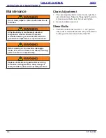
Страница 22: ...bolts secured with locknuts They are located in the flange of the main drive shaft at the PTO Do not clean adjust or service when machine is in motion All hydraulically or mechanically elevated components must be blocked to prevent accidental lowering or must be lowered to the ground when adjustments or repairs are made Before working on this machine disengage tractor PTO shut off tractor and allo...

Страница 23: ...OPERATION AND MAINTENANCE 4 7 TABLE OF CONTENTS INDEX Table provided for general use NOTES ...

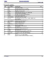
Страница 24: ...5 1 F 1154 2304 Chapter 5 TABLE OF CONTENTS INDEX Parts List Frame Assembly Figure 5 1 Frame Assembly FRONT 2 3 13 4 14 5 15 1 11 6 16 7 17 8 18 9 19 10 20 22 23 24 25 21 27 23 AFTER 1998 ...

Страница 25: ...B 3 12 EPA74013 CUTTER HEAD ASSY BLK D5P D10P INCL ITEMS 15 18 SEE PAGE 5 6 1 13 1 654 010059 03 SCREW 5 8 11UNCX1 1 2 HXCP G 4 14 1 861 010034 15 WASHER LKG HLCL SPR 5 8 4 15 E0938 CUTTER HEAD WELD 16 OD 1 16 E100662 D BLADE 2 HOLES BLACK 4 17 1 654 010056 03 SCREW 1 2 20UNFX1 1 2 8 18 E10498 NUT HEX LOCK 1 2 20 8 19 E0939 STAND WLDMT PARKING BLACK 2 20 516 22PTL RETAINING PIN 2 21 E0937 SKID WLD...

Страница 26: ... CONTENTS INDEX Chain Case Assembly Figure 5 2 Chain Case Assembly 39 2 5 31 5 38 41 4 3 37 33 34 12 13 14 15 1 11 6 16 7 17 8 18 9 19 10 20 22 23 24 25 24 25 21 26 35 32 29 30 10 27 9 10 11 13 34 6 10 27 21 22 20 21 23 23 21 38 28 28 40 ...

Страница 27: ...D 4 21 E10905AGCO FLANGE 6 9 16 OD 4 SQ HOLES 8 22 E11329AGCO O RING 4 1 4 OD 3 7 8 ID 3 16 4 23 E11328AGCO GASKET FLANGETTE 6 9 16 OD 4 24 E11375AGCO SPROCKET DBLE 80 16 TOOTH D10P SPROCKETS TOP E11375AGCO BOTTOM 11376AGCO D5P SPROCKETS TOP 11376AGCO BOTTOM E11375AGCO 1 25 E11376AGCO SPROCKET DBLE 80 22 TOOTH D10P SPROCKETS TOP E11375AGCO BOTTOM 11376AGCO D5P SPROCKETS TOP 11376AGCO BOTTOM E11375...

Страница 28: ...e 5 3 PTO Drive Shaft Power Take Off PTO Drive Shaft ITEM PART NUMBER DESCRIPTION QTY 1 157856 PTO 540 D5P18A 1 3 8 COUPLER SIZE 1 1 157169 PTO 1000 21T TRAC YOKE D10P18 1 3 8 COUPLER SIZE 1 1 157168 PTO 1000 20T TRAC YOKE D10PH18 1 3 4 COUPLER SIZE 1 2 165093 PTO REPAIR KIT NOT SHOWN 1 1 ...

Страница 29: ...Figure 5 4 Cutter Head Assembly Cutter Head Assembly ITEM PART NUMBER DESCRIPTION QTY EPA74013 CUTTER HEAD ASSY BLK D5P D10P 1 1 E0938 CUTTER HEAD WELD 16 OD 1 2 E10498 NUT HEX LOCK 1 2 20 8 3 E100662 D BLADE 2HOLES BLACK 4 4 1 654 010056 03 SCREW 1 2 20UNFX1 1 2 8 2 3 4 1 ...

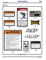
Страница 30: ...M 8 2 573 010198 ITEM 7 162617 ITEM 7 162616 WARNING Operate only with 540 rpm PTO All drive line shields must be kept in place 017805 WARNING Operate only with 1000 rpm PTO All drive line shields must be kept in place 017806 ITEM 2 017805 ITEM 2 017806 ITEM 6 141259 DANGER 366579 ITEM 3 366579 ITEM 5 366578 NOTICE TIGHTEN SETSCREWS FINGER TIGHT TO REMOVE EXCESS CHAIN SLACK DO NOT OVER TIGHTEN SEC...

Страница 31: ... 017805 DECAL WARNING D5P 1 2 017806 DECAL WARNING D10P 1 3 366579 DECAL DANGER 2 4 1 573 010006 PLATE NAME 1 5 366578 DECAL WARNING 1 6 141259 DECAL LANDOLL YELLOW 2 7 162616 DECAL MODEL D5P 1 7 162617 DECAL MODEL D10P 1 8 2 573 010198 DECAL MEMBER FEMA 1 9 7169 380 DECAL CHAIN ADJUSTMENT 1 RIGHT VIEW 2 REAR VIEW RH LH 4 5 6 7 8 3 LEFT VIEW 3 9 Shown with original shield ...

Страница 32: ...5 9 F 1154 2304 PARTS LIST TABLE OF CONTENTS INDEX Table provided for general use NOTES ...

Страница 33: ...Counterweight CVR Cover CYD Cylinder D DBL Double DIA Diameter E ENCLSD Enclosed F FHCS Flanged Head Cap Screw FHHCS Flanged Hex Head Cap Screw FL OR FLG Flange FLT Flat G GA Gauge H HHCS Hex Head Cap Screw HCS High Carbon Steel HD Head HLCL Helical HCSKT Hex Socket HSFC Hex Socket Flat Countersunk HYD Hydraulic I ID Inside Diameter L LH Lefthand LKG OR LOCK Locking LWR Lower M MANF Manifold MNT M...

Страница 34: ...nd RND Round S SER Series SHCS Socket Head Cap Screw SHLD Shield SKT Socket SLFLKG Selflocking SOC Socket SPDT Single Pole Double Throw SPR Spring SQ Square SRTD Serrated SSCR Setscrew SST Stainless Steel STD Standard U UPR Upper W WHL Wheel WLD OR WLDMT Weldment ...

Страница 35: ... 010070 03 5 2 171892 5 2 1 796 010001 5 2 1 861 010032 14 5 4 1 861 010032 15 5 4 1 861 010034 12 5 4 1 861 010034 13 5 4 1 861 010034 15 5 2 1A64139 5 4 1D67947 5 4 1D69248 5 4 1D69249 5 4 2 573 010198 5 8 366575 5 2 366578 5 8 366579 5 8 366758 5 4 516 22PTL 5 2 7064 8 5 4 7169 380 5 8 7223 5 5 4 7458 3 5 4 7650 57 5 4 E E0908 5 2 E0911 5 2 E0937 5 2 E0938 5 2 5 6 E0939 5 2 E100616 5 4 E100640 ...

Страница 36: ...INDEX E11359AGCO 5 4 E11375AGCO 5 4 E11376AGCO 5 4 E11381AGCO 5 4 E11979 5 4 E12017 5 4 E20364 5 4 E6570 5 2 E7397 5 2 EPA74009 5 4 EPA74013 5 2 5 6 W W907051 4 5 4 W908182 4 5 4 W909576 4 5 4 W909902 5 4 W932022 4 5 4 W933232 5 2 W941049 5 4 ...

Страница 37: ...INDEX 7 3 TABLE OF CONTENTS INDEX Table provided for general use NOTES ...

Страница 38: ... NUMBER NOMENCLATURE The serial number for the Power Ditcher is located on the identification plate The following information will help decode the Landoll serial number 30D2200100 xxmyysssss xx model series i e 30 for all Agriculture Seeders m month of manufacture ex D means April The letter I is not used yy last 2 digits of the year manufactured ex 22 means 2022 sssss Sequential number used to tr...

Страница 39: ...ion and Comments 03 2001 F 351 0301 Operator s Manual 02 2002 F 353 0202 Parts Manual 04 2011 F 351 0411 Operator s Manual 04 2011 F 353 0411 Parts Manual 04 2023 F 1154 2304 Revise Manual Combined Operator s and Parts Manual New Template Revised Format Year Month ...

Страница 40: ...ufacturing facilities LANDOLL COMPANY LLC 1900 North Street Marysville Kansas 66508 785 562 5381 800 428 5655 WWW LANDOLL COM Copyright 2023 Landoll Company LLC All rights reserved including the right to reproduce this material or portions thereof in any form Model D5P D10P Operation s and Parts Manual Re Order Part Number F 1154 ...

Отзывы: