background image

3-1

TABLE OF CONTENTS

Chapter 3

Assembly Instructions

It is very important that your new 7822 High Speed 
Landoll () be properly assembled, adjusted and 
lubricated before use. Illustrations in this section show 
proper assembly procedures. Remove paint from grease 
fittings. Replace any grease fittings that are damaged or 
missing. Be sure to return screws, clips, etc., to their 
original locations.

To ensure alignment of assemblies, 

leave the nuts 

loose until completion

 of final assembly. Use lock 

washers or flat washers as specified. Spread all cotter 
pins.

After completion of final assembly, tighten all nuts 
evenly

 to prevent misalignment, distortion or binding. 

Tighten all screws and nuts to the recommended torques 
shown in


“General Torque Specifications (rev. 4/97)” 

on page 2-2

.

DANGER

WARNING

DANGER

CAUTION

Unloading the HSL and 
Final Assembly

I

n most cases the 7822 has come to you with the main 

wheels and tires shipped loose due to shipping width, 
restrictions.

1.

Install the main wheels and tires to the hitch 
rockshaft hubs. 

See Figure 3-2

2.

Due to the being a towed implement the tire tread is 
typically installed opposite of that of a tread where 
power would be applied through it.


NOTE

There is a protruding step on the hub pilot. The wheel 
center plate must fit over the hub pilot and then bottom 
out against the hub flange. Failure to get the wheel 
properly positioned against the hub face will cause the 
wheel to loosen and cause damage to the hub and/or 
wheel. 

3.

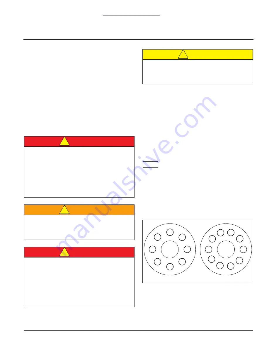
With the tire and wheel assembly correctly positioned 
against the hub, begin to tighten the flange nuts 
sequentially as shown below. 

Figure 3-1:  Lug Nut Tightening Sequence

4.

Re-check the positioning of the wheel relative to the 
hub and proceed by tightening the lug nut assemblies 
sequentially to 450 to 500 foot pounds.

Disc blades are extremely sharp. Exercise 
extreme care when working on or near disc 
blades. Do not allow discs to roll over or fall onto 
any bodily part. Do not allow wrenches to slip 
when working near disc blades. Never push 
wrenches toward disc blades. Do not climb over 
machine above disc blades. Failure to stay clear 
of disc blade edges can cause serious personal 
injury or death.

Do not attempt to lift heavy parts (such as the 
frame, disc gangs, rockshaft, and pull hitch) 
manually. Use a hoist or a fork lift to move these 
parts into position.

To prevent accidental lowering:

All hydraulically elevated equipment must be 
locked out using the cylinder lockouts.

Lower equipment to the ground while 
servicing or when it is idle.

Failure to take measures to prevent accidental 
lowering may result in serious personal injury or 
death.

Be sure to bleed the hydraulic system of all air in 
lines after installation. Failure to bleed the system 
of all air can result in improper machine 
operation.

8 Stud Hub

10 Stud Hub

2

3

4

5

6

7

8

1

2

3

4

5

6

7

8

9

10

1

Содержание 7822 Series

Страница 1: ... Model 7822 High Speed Landoll Operator s Manual LANDOLL CORPORATION 1900 North Street Marysville Kansas 66508 785 562 5381 800 428 5655 WWW LANDOLL COM F 1045 0819 ...

Страница 2: ...Manuals for 7822 HSL Manual Number Manual Name F 1045 Operator s Manual F 1034 Parts Manual ...

Страница 3: ...tion Recommended 2 1 Recommended Torque Specification For Lug Bolts and Nuts 2 1 General Torque Specifications rev 4 97 2 2 Hydraulic Fitting Torque Specifications 2 3 3 Assembly Instructions Unloading the HSL and Final Assembly 3 1 Unfolding the HSL 3 2 Final Assembly 3 3 4 Operation Maintenance Product Description and Operation 4 1 Unfolding the 7822 HSL 4 3 Folding the 7822 HSL 4 3 Synchronizin...

Страница 4: ...ure 4 8 Operating Depths and Adjustments for the Tilt Control Operated HSL 4 9 Operating the HSL with GPS 4 9 Turning On the Headland 4 10 Replacing the Disc Hub Bearing 4 10 Lubrication Maintenance 4 11 Rubber Roller Scraper Adjustment 4 12 5 Troubleshooting ...

Страница 5: ...your equipment before using it and describes adjustments needed Gives practical advice for the care and maintenance of your Landoll equipment Drawings in this section locate adjustment points on the equipment IF YOU HAVE ANY QUESTIONS CONTACT LANDOLL CORPORATION 1900 NORTH STREET MARYSVILLE KANSAS 66508 PHONE 785 562 5381 or 800 428 5655 OR FAX 888 527 3909 Chapter 5 Is a troubleshooting guide to ...

Страница 6: ...emove any dirt or residue Where possible sign placement should protect the sign from abrasion damage or obstruction from mud dirt oil etc DANGER Transporting Safety IMPORTANT It is the responsibility of the owner operator to comply with all state and local laws When transporting the implement on a road or highway use adequate warning symbols reflectors lights and slow moving vehicle sign as requir...

Страница 7: ...be desirable to have your hitch extended IMPORTANT Please consult your dealer if the hitch point is forward of the rear extremity of your tracks 4 Finish connecting the hydraulic couplers Highest priority and most accessible control Red circuit machine tilt circuit Second priority Blue circuit front gauge wheels and depth control Third priority Black circuit rear reel control Fourth priority Yello...

Страница 8: ... be required Chain capacity must be greater then the TOTAL weight of all towed implements A second chain should be used between each implement Attach the chain to the tractor drawbar support or specified anchor location Allow only enough slack in the chain to permit turning The distance from hitch pin to attachment point or intermediate support point should not exceed 9 inches Replace the chain if...

Страница 9: ... 20 240 13 1 25 Front 24 Rear 4 807 LBS 23 583 LBS 7822 23 280 13 1 29 Front 28 Rear 4 953 LBS 24 896 LBS With single chevron reel installed Tire Inflation Recommended Tire Size Tire Manufacturer Ply Load Rating Inflation Pressure Psi Model 710 40R22 5 Goodyear Load Rating 168 156 12 300LBS 46 psi max 40 psi recommended All VF 410 50R16 5 BKT 153 A8 B 73 psi 7822 17 20 23 Recommended Torque Specif...

Страница 10: ...16 12 55 62 80 100 110 137 9 16 18 60 75 90 112 130 162 5 8 11 75 94 110 137 170 212 5 8 18 85 106 130 162 180 225 3 4 10 130 162 200 250 280 350 3 4 16 150 188 220 275 320 400 7 8 9 125 156 320 400 460 575 7 8 14 140 175 360 450 500 625 1 8 190 237 408 506 680 850 1 14 210 263 540 675 760 950 1 1 8 7 270 337 600 750 960 1200 1 1 8 12 300 375 660 825 1080 1350 1 1 4 7 380 475 840 1050 1426 1782 1 ...

Страница 11: ...nd Fittings Dash Size 37 Degree JIC O Ring ORS O Ring Boss ORB 4 11 13 15 17 13 15 5 14 16 21 23 6 20 22 34 36 25 29 8 43 47 58 62 40 44 10 55 65 100 110 58 62 12 80 90 134 146 75 85 16 115 125 202 218 109 121 20 160 180 248 272 213 237 24 185 215 303 327 238 262 32 250 290 310 340 Gates Brand Fittings Dash Size 37 Degree JIC O Ring ORS O Ring Boss ORB 4 10 11 10 12 14 16 5 13 15 6 17 19 18 20 24 ...

Страница 12: ...2 4 F 1045 0819 STANDARD SPECIFICATIONS TABLE OF CONTENTS NOTES ...

Страница 13: ...hub flange Failure to get the wheel properly positioned against the hub face will cause the wheel to loosen and cause damage to the hub and or wheel 3 With the tire and wheel assembly correctly positioned against the hub begin to tighten the flange nuts sequentially as shown below Figure 3 1 Lug Nut Tightening Sequence 4 Re check the positioning of the wheel relative to the hub and proceed by tigh...

Страница 14: ...r proper positioning on pads and proper seating against flange Then Tighten Flange Nuts to recommended torque using sequence shown 3 573 010210 RECOMMENDED TORQUE 450 500FT LBS 8 4 6 2 3 7 5 1 7 5 3 10 8 6 4 9 2 1 DANGER Read and Understand the installation service and safety instructions manual before installing or servicing the hub Failure to do so may result in personal injury or death and may ...

Страница 15: ...me of the rear gauge rockshafts are the same apparent width but may be different in other ways relative to the final assembly 1 Once the rear gauge rockshafts are in place secure the rockshaft bearings with the 3 4 10 x 12 hex screws provided Torque the nuts to approximately two hundred foot pounds 200 ft lbs 2 Once the rear gauge rockshafts are in place secure them to the rear gauge cylinders wit...

Страница 16: ...3 4 F 1045 0819 ASSEMBLY INSTRUCTIONS TABLE OF CONTENTS NOTES ...

Страница 17: ...ades are extremely sharp Exercise extreme care when working on or near disc blades Do not allow discs to roll over or fall onto any bodily part Do not allow wrenches to slip when working near disc blades Never push wrenches toward disc blades Do not climb over machine above disc blades Failure to stay clear of disc blade edges can cause serious personal injury or death All hydraulically elevated e...

Страница 18: ...nished characteristic to the reel roll purchased The depth of the depth gauges is controlled from a single point control just to the left of the tilt cylinder on the hitch The depth control utilizes a master and slave hydraulic cylinder system The down pressure of the reel roller system is controlled from a single point control on the left had wing The setting of the reel roller system utilizes a ...

Страница 19: ...e wing frames several inches above the wing rest saddles located on the hitch The center section is tilted backward by extending the large cylinder located over the hitch red circuit 5 With the wing assemblies just above the wing rest saddles further retract the wing fold cylinders to position the wing assemblies over the wing rest saddles yellow circuit 6 With the wing assemblies over the wing re...

Страница 20: ...e bushings to the top of the top center section frame Confirm the distance to be approximately three and one quarter 3 1 4 inches 4 The wing gauge wheels and tires on the 7822 17 7822 20 and 7822 23 are BKT 410 50R16 5 Adjust the wing gauge wheel cylinder mounts so that the distance from the top of the wing frame to the top of the wing gauge spindle sleeve is six 6 inches more than the measurement...

Страница 21: ... range and then adjust the control from that point until the HSL tracks straight behind the tractor Figure 4 3 Tilt Control Adjustment The front row disc units would cause the HSL to track to the tractors right hand side if they were dominant In the same way the rear disc units would cause the HSL to track to the tractors left hand side if they were dominant If the HSL is tracking to the left side...

Страница 22: ...s wear down you will find it beneficial to adjust the rear gangs to the machines right side When adjusting the rear disc gangs laterally it is best to first set the gang in the direction of the desired movement so that the gangs do not hit each other While the typical row unit spacing is 10 the spacing between the row units at the fold break is approximately 10 3 8 Once the center section rear gan...

Страница 23: ...e leveler is a function of both speed and field conditions loose dirt present It is best to initially adjust the blade leveler to ride at ground level with the bottom edge parallel to the ground If it is set to high the loose dirt will escape underneath the blade and not be delivered to where it is needed If the ground speed will be ten miles per hour or more gap the blade leveler laterally a bit ...

Страница 24: ...raulic wing down pressure manifold is located on the left side of the hitch just inside the frame The hydraulic wing down pressure system needs to be run continuously when the 7822 HSL is working in the field It is recommended that the wing fold circuit yellow circuit be connected to a tractor circuit in which the flow has been reduced to approximately twenty percent 20 of its full capacity Turnin...

Страница 25: ...depth control the rear reels play a major role in the final performance of the HSL If the down pressure on the reels becomes extensive it will have an adverse effect on the overall system If too much down pressure is applied to the rear reels they will hold the rear row of disc units out of the ground This will cause the HSL to track to the left hand side Typically when this is the case the operat...

Страница 26: ...nce the turn is completed lower the HSL back into the field by reversing the tilt cylinder red circuit until its extension is terminated by the tilt control valve Replacing the Disc Hub Bearing 1 The replacement hub and bearing assembly is available as a pre assembled assembly Landoll P N 210880 Should you choose the wear parts are also available in a kit to re build the disc hub Landoll kit 21994...

Страница 27: ...e with 3 5 molybdenum sulfide is recommended Wipe soil from fittings before greasing Replace any lost or broken fittings immediately 4 The wing gauge wheel hubs and the reel bearings are equipped with seals that will let grease purge without harming the seal Regular lubrication will maintain a full grease cavity and help purge any contaminants Grease the bearings before long periods of storage to ...

Страница 28: ...especially during initial use or when returning to duty after have set for a period It is always a good idea to rotate the rubber rollers after making adjustments to assure an adequate clearance between the roller and the scrapers The scrappers will require adjustment periodically as they wear to maintain the proper clearance Figure 4 10 Rubber Roller Scraper Adjustment 6 Main Tilt Cylinder 2 each...

Страница 29: ...fter full extension Front wing gauge wheels not level with center section See Synchronizing and Leveling Front Gauge Points on page 4 3 Rear depth gauge reel roller bearing frozen Replace the bearing assembly Disc tracking to the left behind tractor Rear gangs too deep relative to the front Adjust tilt control counter clockwise Disc tracking to the right behind tractor Front gangs too deep relativ...

Страница 30: ... for 5 to 10 seconds after full extension Hydraulic wing down pressure is not operating correctly Make certain that the indicator gauge is showing the recommended pressure and the flow is not excessive Hydraulic wing down pressure is too high and center section is too light Reduce wing down pressure Hydraulic wing down pressure is too low and the wing tips are too light Increase wing down pressure...

Страница 31: ...nown to work Limit valve on hitch safety circuit not closing b pass circuit Confirm spring plunger to be depressing limit valve plunder when folded forward Hitch safety circuit limit valve leaking and needs replaced Machine will not tilt rear upward or fold Tractor valve not working Try a different tractor circuit known to work Check valve on hitch safety circuit not closing leaking Clean check va...

Страница 32: ...5 4 F 1045 0819 TROUBLESHOOTING TABLE OF CONTENTS NOTES ...

Страница 33: ...Document Control Revision Log Date Form New Updated Improvement s Description and Comments 08 27 2019 F 1045 0819 New Initial Release GG ...

Страница 34: ...ing facilities Model 7822 High Speed Landoll HSL Operator s Manual Re Order Part Number F 1045 0819 LANDOLL CORPORATION 1900 North Street Marysville Kansas 66508 785 562 5381 800 428 5655 WWW LANDOLL COM Copyright 2020 Landoll Corporation All rights reserved including the right to reproduce this material or portions thereof in any form ...

Отзывы: