


Section 4: Maintenance & Lubrication
RTA2562, RTA2570, & RTA3576 Rotary Tillers 311-254M
1/18/21
22
Section 4:
Maintenance & Lubrication
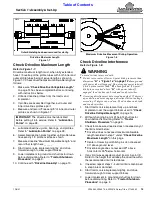
Maintenance
Proper servicing and adjustments are key to the long life
of any implement. With careful inspection and routine
maintenance, you can avoid costly downtime and repair.
Check all hardware after several hours of operation and
regularly thereafter to ensure they are tight and secured.
Replace worn, damaged, or illegible safety labels by
obtaining new labels from your Land Pride dealer.
WARNING
!
To avoid serious injury or death:
DANGER
!
To avoid serious injury or death:
Always secure equipment with solid, non-concrete supports
before working under it. Never go under equipment supported
by concrete blocks or hydraulics. Concrete can break,
hydraulic lines can burst, and/or hydraulic controls can be
actuated even when power to hydraulics is off.
WARNING
!
To avoid serious injury or death:
•
Always follow “Tractor Shutdown Procedure” provided in
this manual before dismounting the tractor.
•
Perform scheduled maintenance. Check for loose
hardware, missing parts, broken parts, structural cracks,
and excessive wear. Make repairs before putting the
•
Do not alter implement or replace parts on the implement
with other brands. Other brands may not fit properly or
meet OEM (Original Equipment Manufacturer)
specifications. They can weaken the integrity and impair the
safety, function, performance, and life of the implement.
Replace parts only with genuine OEM parts.
•
Before any lubrication or maintenance is performed, lower
implement to ground, shut engine off, and remove ignition
key. Do not attempt to lubricate or perform maintenance
with implement or power machine running.
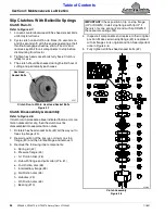
Roller Chain & Drive Sprockets
Sprockets and roller chain should be checked for wear
annually by a qualified person. Replacing a worn roller
chain will extend the life of the sprockets. Be sure to
replace worn sprockets when replacing the roller chain.
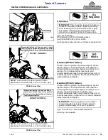
Access roller chain and sprockets through the chain
case.
Refer to Figure 4-1 on page 23:
1. Remove oil level plug (#1). Tip tiller backwards and
drain oil out into an oil drip pan.
2. Loosen chain tightener jam nut (#2) and chain
tightener stud (#3).
3. Placed an oil drip pan under chain case cover (#6)
and remove 1/4"-20 hex bolts (#5).
4. Being careful not to damage gasket (#7), remove
chain case cover (#6).
5. Inspect gasket (#7). Be sure to replace it if it is
damaged.
6. Inspect roller chain (#4) and replace if worn
excessively.
7.
Inspect top sprocket (#9) and bottom sprocket (#10).
Replace if worn excessively.
8. When replacing the bottom sprocket (#10), be sure to
tighten nylock nut (#8) to the correct torque.
Refer to Figure 4-1 & Figure 4-2 on page 23:
9. Tighten nylock jam nut (#8) all the way down until top
sprocket (#9) is bottomed out on the bearing.
10. Back jam nut out until you can install .015" feeler
gauge between sprocket and jam nut as shown.
11. Tighten jam nut up against feeler gauge until snug.
Pull feeler out and tighten jam nut 1/6 of a turn.
Refer to Figure 4-1 on page 23:
12. Install roller chain (#4). Make sure roller chain is
under chain idler arm (#11).
13. Install gasket (#7) and chain case (#6) with 1/4"-20
hex flange serrated screws.
14. Draw all the screws (#5) up snug before tightening
them. Tighten screws to the correct torque as follows:
•
Tighten the bottom screw first.
•
Tighten the next screw up on the right.
•
Cross over to the left and tighten that screw.
•
Continuing crossing back and forth tightening the
screws working your way up the chain case until
you have tightened the top screw.
IMPORTANT:
The top sprocket (#9) requires special
tightening of nylock jam nut (#8) to prevent
premature bearing. damage.
NOTE:
The input shaft on the gearbox should turn
using hand pressure.