Lancaster XFACTOR 7-LX125F-DAN-1B Скачать руководство пользователя страница 19

PAGE 19

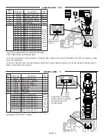
Replace broken or damaged drive gears. Do not lubricate any of the gears. Avoid getting any foreign matter on the reflective coating 

because dirt or oils may interfere with pulse counting. 
The drive gear cover only fits on one way, with the large clip orientated towards the bottom. If all three clips are outside of the gear 

shroud on the drive bracket the drive gear cover slips easily into place. 
The drive bracket does not need to be removed from the drive plate if the motor needs to be removed. To remove the motor, disconnect 

the power and motor plugs from the jacks on the PC board. Move the spring clip loop to the right and hold. Rotate the motor at least a 

¼ turn in either direction so the wires are vertical (up & down) before gently pulling on the wire connectors to remove the motor. Pulling 

directly on the wires without rotating the motor may break the wires off the motor. 
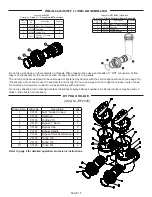
Replace the motor if necessary. Do not lubricate the motor or the gears. To reinstall the motor, move the spring clip loop to the right and 

hold. Gently turn the motor while inserting so that the gear on the motor meshes with the gears under the drive gear cover. Release the 

spring clip loop and continue to rotate the motor until the wires are horizontal and the motor housing engages the small plastic bulge 

inside the drive bracket motor retainer. Reconnect the motor plug to the two-pronged jack on the lower left side of the PC board. If the 

motor will not easily engage with the drive gears when reinstalling, lift and slightly rotate the motor before reinserting. Reconnect the 

power plug.
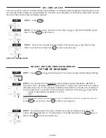
Replace the valve cover. After completing any valve maintenance involving the drive assembly or the drive cap assembly and pistons, 
unplug power source jack from the printed circuit board (black wire) and plug back in or press and hold 

NEXT

 and 

REGEN

 buttons for 3 

seconds.
This resets the electronics and establishes the service piston position. The display should flash the software version and then reset the 

valve to the service position. 

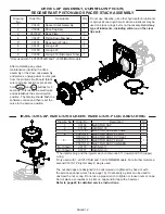
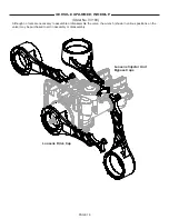
DRIVE CAP ASSEMBLY, MAIN PISTON AND (refer to page 11&12 for diagrams):

The drive assembly must be removed to access the drive cap assembly. The drive cap assembly must be removed to access the 

piston(s). The drive cap assembly is threaded into the control valve body and seals with an o-ring. To remove the drive cap assembly 

use the special plastic service spanner wrench (see page 16) or insert a ¼” to ½” flat blade screwdriver into one of the slots around the 

top 2” of the drive cap assembly so it engages the notches molded into the drive back plate around the top 2” of the piston cavity. See 

figure below. The notches are visible through the holes. Lever the screwdriver so the drive cap assembly turns counter clockwise. Once 

loosened unscrew the drive cap assembly by hand and pull straight out.

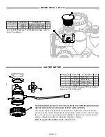
The drive cap assembly contains the drive cap, the main drive gear, drive cap spline, piston rod and various other parts that should not 

be dissembled in the field. The only replaceable part on the drive cap assembly is the o-ring. Attached to the drive cap assembly is the 

main piston (and a regenerant piston for 7-LXCTAIR and 7-LXIMAIR models).
The regenerant piston (the small diameter one behind the main piston found only the 7-LXIMAIR models is removed from the main 

piston by pressing sideways and unsnapping it from its latch. Chemically clean in dilute sodium bisulfite or vinegar, or replace the 

regenerant piston if needed. To remove the main piston fully extend the piston rod and then unsnap the main piston from its latch by 

pressing on the side with the number. Chemically clean in dilute sodium bisulfite or vinegar, or replace the main piston.
Reattach the main piston to the drive cap assembly. Reattach the regenerant piston (if needed) to the main piston. Reinsert the drive 

cap assembly and piston into the spacer stack assembly and hand tighten the drive cap assembly. Continue to tighten the drive cap 

assembly using a screwdriver as a ratchet until the black o-ring on the spacer stack assembly is no longer visible through the drain port. 

Excessive force can break the notches molded into the drive back plate. Make certain that the main drive gear still turns freely. The 

exact position of the piston is not important as long as the main drive gear turns freely.
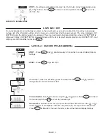
Reattach the drive assembly to the control valve and connect all plugs. After completing any valve maintenance involving the drive 

assembly or the drive cap assembly and pistons, unplug power source jack from the printed circuit board (black wire) and plug back in 
or press and hold 

NEXT

 and 

REGEN

 buttons for 3 seconds.

This resets the electronics and establishes the service piston position. The display should flash the software version and then reset the 
valve to the service position.

Содержание XFACTOR 7-LX125F-DAN-1B

Страница 1: ...documents ELECTRONIC WATER FILTER WITH THE 1 X FACTOR DIAMOND LINE CONTROL VALVE ESTATE SERIES INSTALLATION OPERATING AND SERVICE MANUAL WATER FILTERS AND NEUTRALIZERS ACID NEUTRALIZERS 7 LX125F DAN...

Страница 2: ...structions for 7 LXCTAIR 7 LXIMAIR 7 Placing Filter into Service 8 General Operation 8 Set Time of Day 9 Adjust Days Between Backwash or Time of Backwash 9 10 Low Battery 10 Contact Screen Programming...

Страница 3: ...damage the nut split ring or o ring Solder joints should be cool and solvent cements should be set before installing the nut split ring and o ring Avoid getting primer and solvent cement on any part...

Страница 4: ...lass filled Noryl or equivalent and the nuts and caps are glass filled polypropylene All seals are self lubricating EPDM to help prevent valve seizing after long periods of non use Internal o rings ca...

Страница 5: ...4 When assembling the installation fitting package inlet and outlet connect the fitting to the plumbing system first and then attach the nut split ring and o ring Heat from soldering or solvent cement...

Страница 6: ...HOT LOCATE WATER FILTER CLOSE TO A DRAIN AVOID OVERHEAD DRAIN LINES IF POSSIBLE TO PREVENT BACK PRESSURE ON THE SYSTEM IF OVERHEAD DRAIN LINE IS USED AND EXCEEDS 5 FEET ABOVE CONNECTION ON CONTROL VAL...

Страница 7: ...M BACKWASHES IF THIS IS OBJECTIONABLE A CHECK VALVE CAN BE INSTALLED DIRECTLY AFTER THE AERATION SYSTEM NOTE IF A CHECK VALVE IS INSTALLED BETWEEN A PRESSURE TANK AND A WATER HEATER A HOT WATER EXPANS...

Страница 8: ...allows an air pocket to form for the filter to function properly Control will automatically advance to the FILTERING position Open the outlet valve of the filter or if using optional bypass place to N...

Страница 9: ...and simultaneously for 3 seconds to access Installer Display Settings STEP 2 Day Override Set the maximum number of days between backwashes REGEN If value set to OFF backwash initiation is based solel...

Страница 10: ...digit Banner Text Set the banner text up to a maximum of 44 characters Use the or to select letters of the alphabet numbers ampersand or a space in the banner text Press NEXT to forward to the next ch...

Страница 11: ...sh down to fully seat Battery replacement is 3 volt lithium coin cell type 2032 Correct Battery Orientation 1 2 3 5 6 4 X FACTOR FRONT COVER AND DRIVE ASSEMBLY After completing any valve maintenance i...

Страница 12: ...3 4 5 INJECTOR CAP INJECTOR SCREEN INJEECTOR PLUG AND O RING Drawing No Order No Description Qty 1 V3430 Spacer Stack Assembly 1 2 V3004 Drive Cap Assy 1 3 V3178LP Back Plate 1 4 V3407 Piston Downflo...

Страница 13: ...or tightened by hand or with the service spanner wrench see page 16 If necessary a pliers can be used to unscrew the nut or cap Do not use a pipe wrench to tighten or loosen nuts or caps Do not place...

Страница 14: ...dge Do not use pipe dope or other sealants on threads Teflon tape must be used on threads of 3 4 NPT connection unless using 5 8 polytubing Do not use Vaseline oils other hydrocarbon lubricants or spr...

Страница 15: ...s on threads Teflon tape must be used on threads of 1 NPT connection Teflon tape is not necessary on the nut connection nor caps because of o ring seals The nut and caps are designed to be unscrewed o...

Страница 16: ...tools are necessary to assemble or disassemble the valve the wrench shown in various positions on the valve may be purchased to aid in assembly or disassembly Loosens Injector And Bypass Caps Loosens...

Страница 17: ...der No V3007 07 Description Fitting 1 1 PVC Solvent Assembly Drawing No Order No Description Quantity 1 V3151 Nut 1 Quick Connect 2 2 V3150 Split Ring 2 3 V3105 O Ring 215 2 4 V3352 Fitting 1 1 PVC So...

Страница 18: ...l conditions Pressure drop is very low DRIVE ASSEMBLY refer to pages 11 12 for diagrams Remove the valve cover to access the drive assembly Disconnect the power source plug black wire from the PC boar...

Страница 19: ...seals with an o ring To remove the drive cap assembly use the special plastic service spanner wrench see page 16 or insert a to flat blade screwdriver into one of the slots around the top 2 of the dr...

Страница 20: ...iers if necessary Attached to the injector cap is a screen Remove the screen and clean if fouled The plug and or injector can be pried out with a small screwdriver The plug can be wiped clean If the p...

Страница 21: ...lace meter f Defective PC Board f Replace PC Board 4 Control valve backwashes at wrong time of day a Power outage a Reset time of day If PC Board has battery back up present the battery may be deplete...

Страница 22: ...tion or disconnect power supply from PC Board for 5 seconds and then reconnect b PC Board not properly snapped into drive bracket b Properly snap PC Board into drive bracket and then Press NEXT and RE...

Страница 23: ...NEXT and REGEN buttons for 3 seconds to resynchronize software with piston position or disconnect power supply from PC Board for 5 seconds and then reconnect Then re program valve to proper setting b...

Страница 24: ...PAGE 24 A DIVISION OF C B TOOL CO 1340 MANHEIM PIKE LANCASTER PA 17601 3196 TEL 717 397 3521 FAX 717 392 0266 www lancasterwatertreatment com E mail info lancasterpump com 11 16...

Отзывы: