


Lampert Tools USA
2020
16
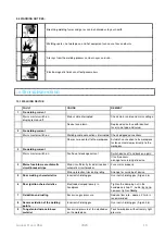
7.3.2. RESISTANCE WELDING
THE BLUE CONNECTION CABLE MAY ONLY BE CONNECTED AFTER THE MODE HAS BEEN ACTIVATED.
AFTER WELDING IS COMPLETE, IT IS VITAL THAT THIS CABLE IS REMOVED AGAIN, BEFORE SWITCHING
TO ANOTHER MODE, IN ORDER TO AVOID FAULTY WELDS!
NOTE: DURING RESISTANCE WELDING, THE FOOT SWITCH FUNCTION IS PERMANENTLY ACTIVATED, AND
CANNOT BE DEACTIVATED!
NOTE: IF TOO LOW A FORCE IS APPLIED TO THE WORKPIECES TO BE CONNECTED, AN ELECTRIC ARC MAY BE
GENERATED, WHICH MIGHT DAMAGE BOTH THE WORKPIECE AND THE ELECTRODES OR OTHER CONTACTING
TOOLS IN USE.
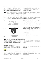
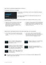
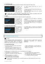
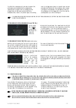
The resistance welding mode can be an option for using
individual solutions, e.g. in combination with a force
controlled triggering of the weld. Corresponding
equipment has to be connected to the socket for the foot
switch*. The following welding curves are available (from
left to right):
1. Single pulse
2. Single pulse with pre-pulse
3. Single pulse with postheating
4. Single pulse with pre-pulse and postheating
5. Single pulse with increased pre-pulse and
postheating
*PLEASE NOTE: Any damage, resulted whilst external equipment or tools, not produced by LAMPERT, were being
connected to PUK-devices, is expressly not covered by our terms of guarantee!
BEFORE SWITCHING TO ANOTHER USER LEVEL, PLEASE REMOVE THE BLUE CONNECTION CABLE
FROM THE PUK U5!
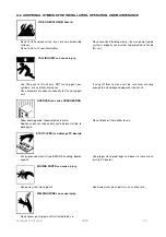
7.4 BASICS AND TIPS
IMPORTANT!
•
Always work with a well sharpened electrode (see point
7-4 for information about sharpening the electrodes).
•
Ensure extremely good contact between the workpiece
and the contact clamp, i.e. make contact between the
workpiece and the connection cable terminal at a point
which is metallically blank.
•
Never weld "free hand", i.e. use the hand rests of the
microscope
SM5.1.
Shaking hands can cause the
configured parameters to be falsified.
•
Apply only light force to the electrode tip.
•
Weld with the correct gas flow of 2
–
3 litres per minute
and check this regularly.
•
With a little experience you will notice that the angle
with which you touch the workpiece with tip of the
electrode affects the "direction of flow" of the welding
point.
•
The electrode can easily be clamped in somewhat
longer for welding recessed areas.
•
In many cases it is helpful to work with welding wire as
a welding supplement, but never with solder.
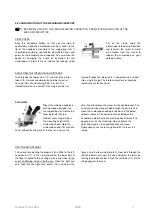
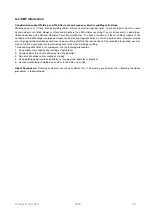
7.5 SHARPENING THE ELECTRODES
Please switch off the machine prior to exchanging
the electrodes. This prevents uncontrolled
triggering of the welding process.
If possible, the electrodes should be sharpened with a
diamond disk with fine or medium grain.
The recommended angle of grinding is approx. 15°.
See also the video “
” on
www.youtube.com/LampertWelding
Содержание PUK U5
Страница 1: ...Operating manual PUKU5 ...


