background image

65

ES

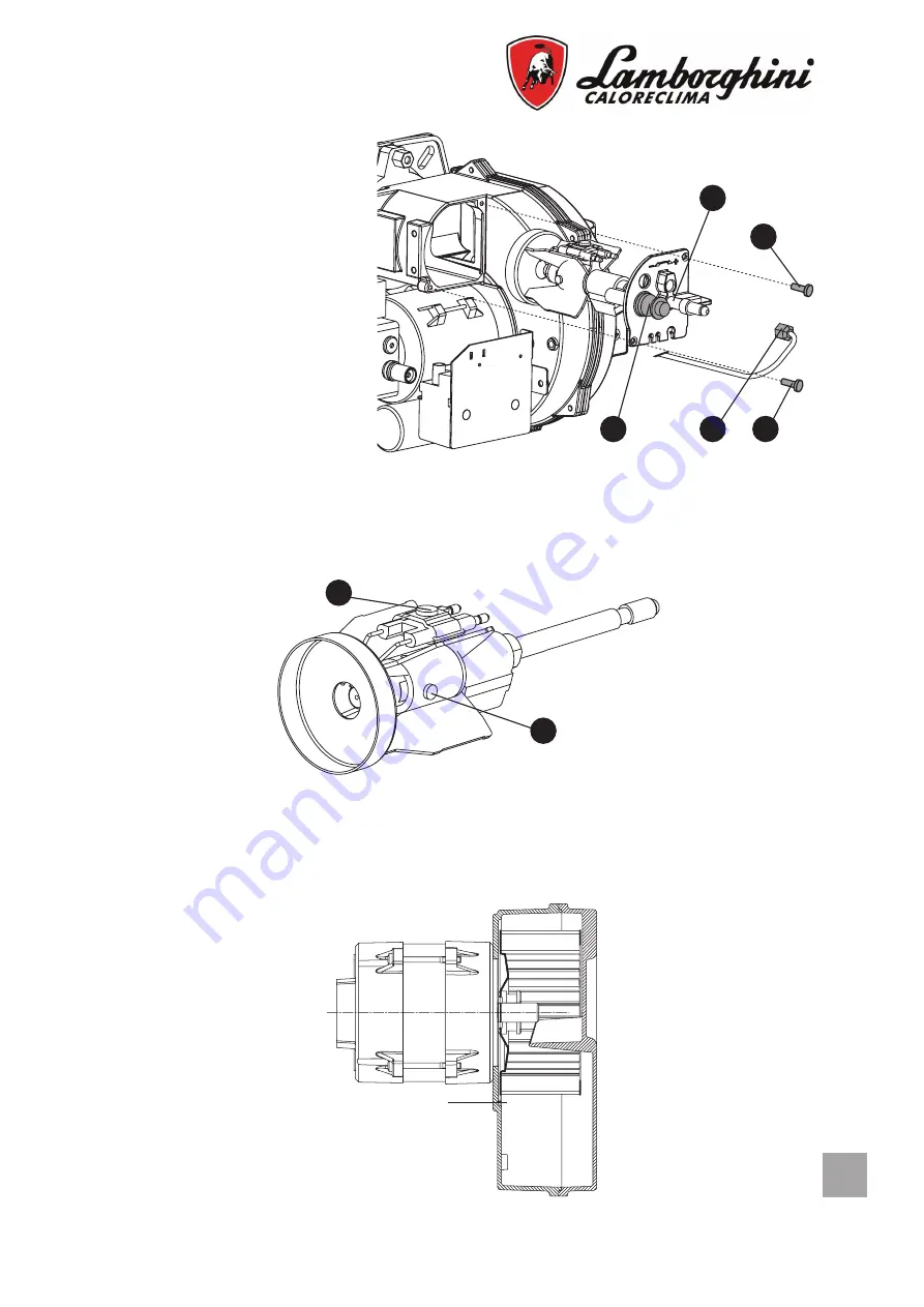
ELECTRODOS INYECTOR

Una vez que se ha procedido 

a retirar el chasis, extraer los 

cables de alta tensión desde el 

lado del transformador, extraer 

la fotoresistencia 

1

, desajustar 

el empalme 

2

 que conecta el 

tubo del gasóleo a la línea 

3

 del 

inyector, desajustar los tornillos 

y extraer el grupo brida-inyector-

deflector-electrodos.

3

2

4

1

4

VENTILADOR

ATTENTION: En cas de remplacement ou de démontage-montagedu rotor de ventilation, 

contrôler que ce dernier ne touche pas le plan du cuerpo del quemador en respectant les 

indications ci-jointes.

Quitar el tornillo 

5

, para retirar el deflector y el tornillo 

6

 para retirar los electrodos. Una 

buena limpieza del inyector se obtiene desmontando el filtro, limpiando los cortes y el foro 

de pulverizado con bencina y enjuagando por último con gasóleo. Volver a montar la unidad 

tratando de conservar el correcto posicionamiento de los electrodos-deflector.

5

6

0,5 ÷1

Содержание FOCUS PRO 3

Страница 1: ...OIL BURNER BRULEURS A FIOUL DOMESTIQUE A UNE ALLURE QUEMADOR DE GAS LEO DE UNA ETAPA MANUALE DI INSTALLAZIONE E MANUTENZIONE INSTALLATION AND MAINTENANCE MANUAL NOTICE D INSTALLATION ET D ENTRETIEN M...

Страница 2: ......

Страница 3: ...ut by qualified personnel who will be responsible for respecting existing safety regulations FRANCAIS 35 Lire attentivement le mode d emploi et les instructions du pr sent livret car ils fournissent d...

Страница 4: ...ori godono di una GARANZIA SPECIFICA a partire dalla data di convalida da parte del Servizio di Assistenza della Sua Zona La invitiamo quindi a rivolgersi tempestivamente al suddetto I bruciatori sono...

Страница 5: ...da un centro di assi stenza autorizzato dalla casa costruttrice utilizzando esclusivamente ricambi originali Il mancato rispetto di quanto sopra pu compromettere la sicurezza dell apparecchio Per gar...

Страница 6: ...predispo sto come indicato sulla targhetta con i dati caratteristici e nelle caratteristiche tecniche fornite in questo manuale Inoltre dovr essere dotato di tutti i meccanismi di controllo e sicurez...

Страница 7: ...regolamentazioni vigenti in materia di elettricit Dopo aver tolto tutti i materiali dall imballo controllare i contenuti ed assicurarsi che questi non siano stati in alcun modo danneggiati durante il...

Страница 8: ...5 80 85 135 160 M8 170 144 CURVE DI LAVORO Le curve rappresentate in diagramma sono state ottenute effettuando le prove di combustio ne secondo le specifiche e le caratteristiche di focolare previste...

Страница 9: ...3 6 3 6 3 F Trasformatore di accensione tensione corrente secondario 15 40 15 40 15 40 15 40 kV mA Grado di protezione elettrica 20 20 20 20 IP Rumorosit 61 61 61 61 dB A Peso 10 10 1 10 10 1 kg Press...

Страница 10: ...mpada di blocco e o contaore ATTENZIONE non scambiare il neutro con la fase eseguire un buon collegamento di terra FOCUS PRO 3 FOCUS PRO 6 Legenda CO Contaore F Fusibile FA Filtro antidisturbo FR Foto...

Страница 11: ...Contaore F Fusibile FA Filtro antidisturbo FR Fotoresistenza IG Interruttore generale LS Lampada di sicurezza MA Morsettiera apparecchiatura MB Motore bruciatore PB Presa bruciatore PR Preriscaldator...

Страница 12: ...5 3 90 32 62 34 63 36 76 38 78 40 92 42 69 44 47 46 25 1 00 3 10 3 30 3 50 3 67 3 85 4 02 4 20 4 38 36 76 39 13 41 51 43 52 45 66 47 67 48 72 51 95 1 25 3 85 4 12 4 40 4 61 4 82 5 03 5 25 5 46 45 66 4...

Страница 13: ...nsione il bruciatore si mette in funzione e resta acceso fino a che non si raggiunta la temperatura prestabilita sull apparecchiatura di comando che inter verr per prima termostato caldaia termostato...

Страница 14: ...ressione 5 Attacco manometro 1 8 6 Attacco vacuometro 1 8 ITALPUMP DANFOSS 4 5 5 6 6 3 3 3 2 2 1 4 REGOLAZIONE SERRANDA ARIA Dopo aver allentato la vite 3 agendo sulla vite 1 si ottiene la regolazione...

Страница 15: ...ulsante di sblocco dell apparecchiatura l elemento principale per poter accedere a tutte le funzioni di diagnostica attivazione e disattivazione oltre a sbloccare il dispositivo di co mando e controll...

Страница 16: ...atura del bruciatore assenza di combustibile 8 lampeggi Anomalia del tempo preriscaldamento de combustibile 9 lampeggi Libero 10 lampeggi Errori di collegamento elettrico o danni all apparecchiatura M...

Страница 17: ...i sufficiente svitare la vite 1 e togliere il cofano Per accedere alla ventola svitare le 4 viti 2 del semicorpo aria del bruciatore Togliendo il coperchio aspirazione aria 3 tramite le 3 viti 4 si ac...

Страница 18: ...ogliere il deflettore e la vite 6 per togliere gli elettrodi Una buona pulizia dell ugello si ottiene smontando il filtro e pulendo i tagli ed il foro di polverizzazione con ben zina e risciacquarlo c...

Страница 19: ...che chiuse lungo la linea gasolio Il bruciatore si avvia Si ha formazione della fiamma e poi si arresta in blocco 1 Fotoresistenza sporca 1 Pulire la fotoresistenza 2 Ugello che polverizza male 2 Puli...

Страница 20: ...ied service and maintenance of the boiler CONFORMITY INDEX The burners are in conformity with 2006 42 EC Machinery Directive 2014 30 EU Electromagnetic Compatibility EMC 2014 35 EU Low Voltage Directi...

Страница 21: ...order to guarantee the efficiency of the appliance and its correct functioning it is indispen sable to follow the manufacturer s indications Have qualified professional staff perform periodic maintena...

Страница 22: ...earth plant in compliance with Standards in force The earth cable must be a couple of cm longer that the phase and neutral wire If in doubt regarding efficiency it must be checked and controlled by q...

Страница 23: ...2 1 4 1 6 mbar 20 40 60 80 100 120 140 160 PA 10 0 0 1 0 Focus Pro 6 Focus Pro 6R Focus Pro 3 Focus Pro 3R Output Combustion chamber pressure Model A B C D E F G H I L M min max FOCUS PRO 3 280 305 2...

Страница 24: ...F Trasformator voltage secondary current 15 40 15 40 15 40 15 40 kV mA Electric protection rating 20 20 20 20 IP Noise level 61 61 61 61 dB A Peso 10 10 1 10 10 1 kg Sound pressure measured in the man...

Страница 25: ...onnection VE FR LS N PB SC TC TA B4 T2 T1 L1 S3 N CO H Z N N L IG F TS M MB FA TR 1 2 2 2 3 4 5 6 7 8 9 10 11 12 MA FOCUS PRO 3 FOCUS PRO 6 Key CO Hour meter F Fuse FA Anti interference filter FR Phot...

Страница 26: ...S PRO 3R FOCUS PRO 6R Key CO Hour meter F Fuse FA Anti interference filter FR Photoresistance IG Main switch LS Safety lamp MA Control box MB Burner motor PB Burner connector PR Preheater SC Plug TA T...

Страница 27: ...5 65 82 68 78 71 75 74 72 77 68 1 75 5 40 5 69 6 18 6 46 6 75 7 06 7 38 7 96 64 04 67 48 73 29 76 61 80 05 83 73 87 53 91 20 2 00 6 20 6 63 7 07 7 43 7 75 8 10 8 42 8 80 73 53 78 63 83 85 88 12 91 92...

Страница 28: ...tch to ON After the pre ignition time has elapsed the burner starts running and stays on until the temperature set on one of the control devices causes the latter to trip boiler thermostat room thermo...

Страница 29: ...4 Pressure adjustment 5 Pressure gauge port 1 8 6 Vacuum gauge port 1 8 ITALPUMP DANFOSS 4 5 5 6 6 3 3 3 2 2 1 1 4 AIR FLAP ADJUSTMENT After having untightened the screw 3 whith the screw 1 it obtain...

Страница 30: ...espect of the environment The release pushbutton on the equipment is the main component for accessing all the dia gnostic functions activation and deactivation as well as for releasing the control and...

Страница 31: ...no fuel 8 flashes Anomalies in fuel preheating time 9 flashes Not used 10 flashes Incorrect electrical connection or damage to equipment MAINTENANCE WARNING All operations should be performed with the...

Страница 32: ...onents simply unscrew the screw 1 and remove the cover To access the fan unscrew the 4 screws 2 of the semi body air burner By removing the air intake cover 3 through the 3 screws 4 you can access the...

Страница 33: ...eplacement or assembly disassembly of the fan make sure that the latter does not touch the body burner platform as illustrated in the inclosed diagram 3 2 4 1 4 Remove a screw 5 in order to remove the...

Страница 34: ...line The burner starts There is the formation of the flame and then stops in block 1 Photoresistance is dirty 1 Clean the photoresistance 2 Nozzle is pulverizing badly 2 Clean or replace nozzle Flame...

Страница 35: ...de l entretien et de la maintenance de nos appareils CONFORMIT INDEX Les br leurs sont conformes Directive Machines 2006 42 CE Directive Compatibilit Electromagn tique 2014 30 UE Directive Basse Tens...

Страница 36: ...nnellement qualifi La r paration ven tuelle des produits ne devra tre effectu e que par un Service apr s vente agr par le fabricant en utilisant exclusivement des pi ces d tach es d origine Le non res...

Страница 37: ...ustion La poussi re est extr mement nuisible en particulier lorsqu elle se d pose sur les pales du ventilateur r duisant la ventilation et don nant lieu une combustion polluante La poussi re peut gale...

Страница 38: ...t de la porte de la chaudi re Les connexions lectriques doivent tre r alis es exclusivement par un personnel qualifi et doivent tre conformes aux r glementations en vigueur en mati re d lectricit Apr...

Страница 39: ...2 0 4 0 6 0 8 1 1 2 1 4 1 6 mbar 20 40 60 80 100 120 140 160 PA 10 0 0 1 0 Focus Pro 6 Focus Pro 6R Focus Pro 3 Focus Pro 3R Puissance termique Pression dans la chambre de combustion Mod le A B C D E...

Страница 40: ...6 3 6 3 6 3 6 3 F Transformateur tension courant secondaire 15 40 15 40 15 40 15 40 kV mA Degr de protection lectrique 20 20 20 20 IP Bruit 61 61 61 61 dB A Poids 10 10 1 10 10 1 kg Pression acoustiq...

Страница 41: ...hermostats ventuelle t moin de blocage et ou compte heures ATTENTION ne pas changer le neutre avec la phase r aliser un bon branchement de terre L gende CO Compte heures F Fusible FA Filtre antiparasi...

Страница 42: ...mpte heures F Fusible FA Filtre antiparasite FR Photor sistance IG Int rrupteur g n ral LS T moin de s curit MA Bornier du coffret de s curit MB Moteur brule r PB Prise brule r PR Pr chauffeur SC Fich...

Страница 43: ...47 46 25 1 00 3 10 3 30 3 50 3 67 3 85 4 02 4 20 4 38 36 76 39 13 41 51 43 52 45 66 47 67 48 72 51 95 1 25 3 85 4 12 4 40 4 61 4 82 5 03 5 25 5 46 45 66 48 86 52 18 54 67 57 16 59 65 62 26 64 75 1 50...

Страница 44: ...n intervenant sur l interrupteur principal Apr s le temps de pr allu mage le br leurse met en marche et reste allum aussi longtemps que la temp rature pr fix e sur le coffret de s curit qui est le pre...

Страница 45: ...piration 1 4 2 Retour 1 4 3 Raccord fioul domestique 1 8 4 R glage de pression 5 Raccord manom tre 1 8 6 Raccord vacuom tre 1 8 REGLAGE CLAPET D AIR Apr s avoir d ss r la vis 3 avec la vis 1 on a la r...

Страница 46: ...ton de d clenchement de l appareil est l l ment principal pour pouvoir acc der toutes les fonctionsde diagnostic activation et d sactivation et pour pouvoir d bloquer le dispositif de commande et de c...

Страница 47: ...ur de flamme D fectuosit au niveau du r glage du br leur absencede combustible 8 clignotements Irr gularit du temps de pr chauffage du combustible 9 clignotements Libre 10 clignotements Erreurs au niv...

Страница 48: ...suffit de d visser la vis 1 et d enlever le capot Pour acc der au ventilateur d vissez les 4 vis 2 du demi corps d air du br leur En enlevant le couvercle d entr e d air 3 travers les 3 vis 4 on acc d...

Страница 49: ...s de remplacement ou de d montage montagedu rotor de ventilation contr ler que ce dernier ne touche pas le plan du corps du br leur en respectant les indica tions ci jointes Devisser la vis 5 pour enl...

Страница 50: ...de la ligne fioul Le br leur s allume La flame seforme puis il s arr te en s curit 1 Photor sistance sale 1 Nettoyer la photor sistance 2 Le gicleur qui pulv rise mal 2 Nettoyer ou substituer le gicl...

Страница 51: ...INYECTOR 59 INSTALACI N 60 REGULACIONES 60 CONTROL COMBUSTION 62 EQUIPO LMO 62 MANTENIMIENTO 63 BUSQUEDA FALLOS 66 Le damos las gracias por haber preferido uno de nuestros productos LAMBORGHINI CALORE...

Страница 52: ...bstenerse de realizar cualquier reparaci n u operaci n directa sobre el mismo Ponerse en contacto solamente con personal cualificado Las reparaciones deben ser efectuadas solamente por un centro de as...

Страница 53: ...ti n El polvo tambi n se puede acumular en la parte posterior del disco de estabilidad de la llama en la cabeza de combusti n y provocar una mezcla de aire escaso combustible El quemador debe alimenta...

Страница 54: ...caldera Las conexiones el ctricas solamente deben ser efectuadas por personal cualificado respe tando totalmente las disposiciones en vigor Despu s de quitar el material de embalaje controlar el conte...

Страница 55: ...2 0 4 0 6 0 8 1 1 2 1 4 1 6 mbar 20 40 60 80 100 120 140 160 PA 10 0 0 1 0 Focus Pro 6 Focus Pro 6R Focus Pro 3 Focus Pro 3R Potencia t rmica Presi n en c mara de combusti n Tipo A B C D E F G H I L M...

Страница 56: ...ondensador 6 3 6 3 6 3 6 3 F Transformador tensi n corriente secondario 15 40 15 40 15 40 15 40 kV mA Grado de protecci n el ctrica 20 20 20 20 IP Ruido 61 61 61 61 dB A Peso 10 10 1 10 10 1 kg Presi...

Страница 57: ...ierra VE FR LS N PB SC TC TA B4 T2 T1 L1 S3 N CO H Z N N L IG F TS M MB FA TR 1 2 2 2 3 4 5 6 7 8 9 10 11 12 MA FOCUS PRO 3 FOCUS PRO 6 Descripci n CO Cuentahoras F Fusible FA Filtro antiinterferencia...

Страница 58: ...Cuentahoras F Fusible FA Filtro antiinterferencia FR Fotorresistencia IG Interruptor general LS Lampara seguridad MA Regleta de borners programador MB Motor quemador PB Conector quemador PR Precalent...

Страница 59: ...3 75 3 90 32 62 34 63 36 76 38 78 40 92 42 69 44 47 46 25 1 00 3 10 3 30 3 50 3 67 3 85 4 02 4 20 4 38 36 76 39 13 41 51 43 52 45 66 47 67 48 72 51 95 1 25 3 85 4 12 4 40 4 61 4 82 5 03 5 25 5 46 45...

Страница 60: ...sa PUESTA EN FUNCIONAMIENTO Efect e el rearme mediante el bot n Encienda el interruptor general Tras el tiempo de preencendido el quemador se pone en funcionamientoy se queda encendido hasta que no se...

Страница 61: ...ida gasoleo 1 8 4 Regulaci n presi n 5 Conexi n de man metro 1 8 6 Conexi n del vacu metro 1 8 REGULACION CLAPETA AIRE Despues de haber aflojado el tornillo 3 interviniendo en el tornillo 1 se obtiene...

Страница 62: ...El pulsador de desbloqueo del equipo es el elemento principal para poder acceder a todas las funciones deldiagn stico activaci n y desactivaci n adem s de desbloquear el disposi tivo de mando y contr...

Страница 63: ...el quemador falta combu stible 8 destellos Anomal a del tiempo de precalentamiento del combustible 9 destellos Libre 10 destellos Errores en la conexi n el ctrica o equipo da ado MANTENIMIENTO ATENCI...

Страница 64: ...sque el tornillo 1 y retire la tapa Para acceder al ventilador desatornille los 4 tornillos 2 del medio cuerpo del aire del quemador Al retirar la tapa de entrada de aire 3 a trav s de los 3 tornillos...

Страница 65: ...ATTENTION En cas de remplacement ou de d montage montagedu rotor de ventilation contr ler que ce dernier ne touche pas le plan du cuerpo del quemador en respectant les indications ci jointes Quitar e...

Страница 66: ...lo largo de la l nea gasoleo El quemador se accio na Se forma la llama y luego se detiene en bloque 1 Fotorresistencia sucia 1 Limpiar la fotorresistencia 2 Inyector pulveriza mal 2 Limpiar o reempla...

Страница 67: ......

Страница 68: ...es modifications qu elle retient le plus necessai res pour l evolution du produit Las ilustraciones y los datos son indicativos y no comprometen Lamborghini Caloreclima se reserva el derecho de realiz...

Отзывы: