

EM 35-E EM 40/2-E EM 40/M-E
MANUALE DI
INSTALLAZIONE E
MANUTENZIONE
INSTALLATION AND
MAINTENANCE
MANUAL
NOTICE
D’INSTALLATION
ET D’ENTRETIEN
INSTALLATIONS-
UND
WARTUNGSANLEITUNG
MANUAL PARA LA
INSTALACIÓN Y EL
MANTENIMIENTO
ΕΓΧΕΙΡΙΔΙΟ
ΕΓΚΑΤΑΣΤΑΣΗΣ
Σ
Η
Σ
Η
Ρ
Η
Τ
Ν
Υ
Σ
Ι
Α
Κ
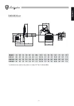
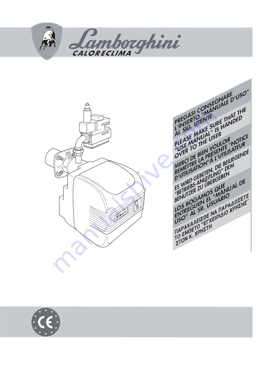
BRUCIATORI AD ARIA SOFFIATA PER CALDAIE NORMALI
FORCED DRAUGHT BURNERS FOR STANDARD BOILERS
BRULEURS A AIR SOUFFLE POUR CHAUDIERES CLASSIQUES
GEBLÄSEBRENNER FÜR NORMALE HEIZKESSEL
QUEMADORES DE AIRE FORZADO PARA CALDERAS NORMALES
AZIENDA CERTIFICATA EN ISO 9001
Содержание EM 40/2-E
Страница 2: ......
Страница 25: ...25 ITALIANO...
Страница 47: ...47 ENGLISH...
Страница 69: ...69 FRAN AIS...
Страница 91: ...91 DEUTSCH...
Страница 113: ...113 ESPA OL...
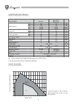
Страница 115: ...115 a b c d CO2 CO2 CO2...
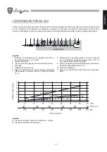
Страница 116: ...116 119 133...
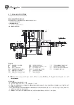
Страница 120: ...120 2 n 4 3 4 5 1 A B C D...
Страница 121: ...121 2...
Страница 126: ...126 3 sec 3 sec LME 10...
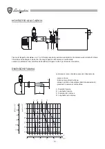
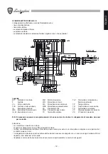
Страница 127: ...127 B 1 2 3 B H EM 35 E H H EM 40 2 E EM 40 M E H fi 1 max E E 1 E 2 E VE 2 2 14 10 13 SQN 71...
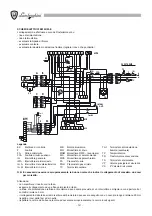
Страница 131: ...131 V pBr pL pBr pBr pF pL pL pF N V 1 1 Offset pBr pL H H H VPS 504 fi MULTIBLOC H H H 1 CO 10 000 p p m 40...
Страница 132: ...132 3 A CO2 CO2 CO2 8 5 10 11 12 B P CO CO CO 0 1 160 C 220 C TPR TS B P...
Страница 134: ...134 1 A B A B 2 A B C A B C 3 A A...
Страница 135: ......


