background image

ALHENA C

196

cod. 3540000251  -  Rev. 00  -  03/2024

PL

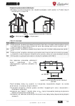
W przypadku po

áą

czenia wspó

á

osiowego nale

Ī

y zainstalowa

ü

 urz

ą

dzenie z jednym z

nast

Ċ

puj

ą

cych akcesoriów wyj

Ğ

ciowych. Wymiary otworów 

Ğ

ciennych mo

Ī

na znale

Ĩü

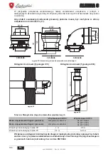
 na rysunku

na ok

á

adce.

Aby u

á

atwi

ü

 ewakuacj

Ċ

 kondensatu przewody poziome musz

ą

 by

ü

 nachylone w stron

Ċ

urz

ą

dzenia na minimum 5% (3°).

wygl

ą

d 22- Akcesoria wyj

Ğ

ciowe do przewodów wspó

á

osiowych

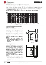
Odleg

á

o

Ğü

 ko

Ĕ

cówki (Typologia C13)

wygl

ą

d 23

Odleg

á

o

Ğü

 ko

Ĕ

cówki (Typologia C33)

wygl

ą

d 24

Tabela 4- Maksymalna d

á

ugo

Ğü

 przewodów wspó

á

osiowych

W zakresie od d

á

ugo

Ğ

ci minimalnej do d

á

ugo

Ğ

ci maksymalnej kominów opisanych w tabeli,

warto

Ğ

ci mocy i spalania zadeklarowane w tabeli danych technicznych b

Ċ

d

ą

 przestrzegane

w granicach tolerancji okre

Ğ

lonych w normie EN15502.

041006X0

041084X0

041083X0

Ø 80

Ø 127

120

147

Ø 100

Ø 60

Ø 60 Ø 100

50 mm

400 mm

Wspó

á

osiowa 60/100

Wspó

á

osiowa 80/125

Maks. dopuszczalna d

á

ugo

Ğü

 (pozioma)

Wszystkie modele 

7

 m

24 kW = 

28

 m

28 kW = 

20

 m

34 kW = 

20

 m

Maks. dopuszczalna d

á

ugo

Ğü

 (pionowa)

Wszystkie modele 

8

 m

Wspó

á

czynnik redukcyjny kolana 90°

1 m

0,5 m

Wspó

á

czynnik redukcyjny kolana 45°

0,5 m

0,25 m

Содержание ALHENA C

Страница 1: ...PER L USO L INSTALLAZIONE E LA MANUTENZIONE INSTRUCCIONES DE USO INSTALACI N Y MANTENIMIENTO INSTRUC IUNI DE UTILIZARE INSTALARE I NTRETINERE INSTRUKCJA OBS UGI INSTALACJI I KONSERWACJI INSTRUCTIONS F...

Страница 2: ...H DVVLFXUDQGR OD WXWHOD GHOOD VDOXWH 3HU XOWHULRUL LQIRUPD LRQL VXOOH PRGDOLWj GL UDFFROWD GHL UL XWL GL DSSDUHFFKLDWXUH HOHWWULFKH HG HOHWWURQLFKH q QHFHVVDULR ULYROJHUVL ai Comuni o alle Autorit pub...

Страница 3: ...io non devono essere lasciati alla portata di bambini in quanto potenziali fonti di pericolo L apparecchio pu essere uti lizzato da bambini di et non inferiore a 8 anni e da persone con ridotte capaci...

Страница 4: ...idraulici 12 2 4 Collegamento gas 14 2 5 Collegamenti elettrici 15 2 6 Condotti fumi 19 2 7 Collegamento scarico condensa 34 3 Servizio e manutenzione 35 3 1 Regolazioni 35 3 2 Messa in servizio 44 3...

Страница 5: ...lo comandi fig 1 Pannello di controllo Legenda pannello fig 1 1 Tasto decremento impostazione tem peratura acqua calda sanitaria 2 Tasto incremento impostazione tempe ratura acqua calda sanitaria 3 Ta...

Страница 6: ...4 il display visualizza il codice di guasto part 12 fig 1 e du rante i tempi di attesa di sicurezza le scritte d3 e d4 1 3 Collegamento alla rete elettrica accensione e spegnimento Caldaia non aliment...

Страница 7: ...io e riscaldamento Rimane attivo il sistema antigelo Per riaccendere la caldaia premere nuovamente il tasto inverno esta te off part 7 fig 1 fig 8 La caldaia sar immediatamente pronta in modalit Inver...

Страница 8: ...verno Estate off part 7 fig 1 fig 10 Regolazione temperatura riscaldamento Agire sui tasti riscaldamento part 3 e 4 fig 1 per variare la temperatura da un mini mo di 20 C ad un massimo di 80 C fig 11...

Страница 9: ...esterne in modo da garantire un elevato comfort e risparmio energetico durante tutto il periodo dell anno In particolare all aumentare della tempe ratura esterna viene diminuita la temperatura di man...

Страница 10: ...ta rio La regolazione pu essere eseguita sia dal men del Cronocomando Remoto sia dal pannello comandi caldaia Commutazione Estate Inverno La modalit Estate ha priorit su un eventuale richiesta riscald...

Страница 11: ...opola di carico Scarico impianto Per scaricare l impianto applicare un tubo in gomma rif 3 fig 16 all attacco della val vola di scarico del circolatore Con l utilizzo di una chiave esagonale aprire e...

Страница 12: ...ddetti a camera stagna L apparecchio idoneo al funzionamento in luogo parzialmente protetto vedi Installazione in luo go parzialmente protetto a pag 27 Il luogo di installazione deve comunque essere p...

Страница 13: ...uro fig 18 Kit idraulico Caratteristiche dell acqua impianto ALe caldaie ALHENA C sono idonee all installazione in sistemi di riscaldamento con ingres so di ossigeno non significativo rif sistemi caso...

Страница 14: ...spositivo non attivo se viene tolta alimentazione elettrica e o gas all apparecchio Se necessario utilizzare per la protezione dell impianto idoneo liquido antigelo che risponda agli stessi requisiti...

Страница 15: ...eventuali danni causati dalla mancanza di messa a terra dell impianto La caldaia precablata e dotata di cavo di allacciamento alla linea elettrica di tipo tripolare sprovvisto di spina I col legamenti...

Страница 16: ...contatti di inter ruzione La loro alimentazione deve essere effettuata tra mite collegamento diretto dalla rete o tramite pile a seconda del tipo di dispositivo Accesso alla morsettiera elettrica e a...

Страница 17: ...17 cod 3540000251 Rev 00 03 2024 IT ALHENA C Seguendo le indicazioni di fig 20 possibile accedere al fusibile F fig 20 F...

Страница 18: ...rcuito di riscaldamento viene ripristinata al livello normale dopo un riem pimento manuale o da comando 3 Gestisce una valvola 3 vie solare I contatti vengono chiusi quando la modalit sanitario attiva...

Страница 19: ...O 00 LI E U0 Avvertenze L apparecchio di tipo C a camera stagna e tiraggio forzato l ingresso aria e l uscita fumi devo no essere collegati ad uno dei sistemi di evacuazione aspirazione indicati di se...

Страница 20: ...anza del terminale Tipologia C33 fig 24 Tabella 4 Massima lunghezza condotti coassiali Dalla lunghezza minima alla lunghezza massima dei camini descritti in tabella i valori di potenza e combustione d...

Страница 21: ...i uscita 2 Consultare la tabella 7 ed individuare le perdite in meq metri equivalenti di ogni componente a seconda della posizione di installazione 3 Verificare che la somma totale delle perdite sia i...

Страница 22: ...8 90 M F 1KWMA01W 1 5 2 0 TRONCHETTO con presa test 1KWMA70W 0 3 0 3 TERMINALE aria a parete 1KWMA85A 2 0 fumi a parete con antivento 1KWMA86A 5 0 CAMINO Aria fumi sdoppiato 80 80 010027X0 12 0 Solo...

Страница 23: ...041050X0 per il 60 Tubo flessibile Si possono utilizzare al massimo 4 metri di camino 80 mm tra la caldaia e il passaggio al dia metro ridotto 50 o 60 e al massimo 4 metri di camino 80 mm sull aspiraz...

Страница 24: ...comburente viene immessa tramite un se condo condotto con proprio terminale diret tamente dall esterno Il ventilatore posizionato a monte del cir cuito di combustione Per le temperature e le portate f...

Страница 25: ...ercapedine da con dotto di aspirazione dell aria comburente Il ventilatore posizionato a monte del circuito di combustione Per le temperature e le portate fumi fare riferimento alla Tabella dati tecni...

Страница 26: ...ONE Il ventilatore posizionato a monte del circuito di combustione Per le temperature e le portate fumi fare ri ferimento alla Tabella dati tecnici a pag 56 fig 35 Per le installazioni tipo B23 Aspira...

Страница 27: ...con temperatura minima di 5 C La caldaia deve essere installata in posizione riparata ad esempio sotto lo spiovente di un tetto all interno di un balcone o in una nicchia riparata Se dotato dell appo...

Страница 28: ...mperature inferiori a 5 C e fino a 15 C la caldaia deve essere dotata dell apposito kit antigelo per la protezione del circuito Collegare il kit alla scheda elettronica nella connessione indicata nell...

Страница 29: ...attaccare in modo VISIBI LE la targhetta adesiva bianca presente nella busta documenti fornita con l ap parecchio al pannello frontale della cal daia BUna volta completata l installazione verificare...

Страница 30: ...tivo per ciascun punto di connessione B Quando il modulo caldaia scollegato le aperture di uscita aria e ingresso prodotti della combustione de vono essere chiuse e verificata la tenuta AIl collegamen...

Страница 31: ...31 cod 3540000251 Rev 00 03 2024 IT ALHENA C Esempio di installazione tipo C 10 3 fig 40 min 0 6 m max 10 m 5...

Страница 32: ...ALHENA C 32 cod 3540000251 Rev 00 03 2024 IT Esempio di installazione tipo C 11 3 fig 41 min 0 6 m max 10 m 5...

Страница 33: ...ni C 10 3 e C 11 3 BLa VALVOLA CLAPET rif A fig 43 codice 041106X0 PU ESSERE INSTALLATA E UTILIZZATA SOLAMENTE IN MODO VERTICALE B Prima di utilizzare l apparecchio necessario riempire d acqua il sifo...

Страница 34: ...esistenti alle condense acide e per mettere sempre il deflusso della condensa prodotta dalla caldaia Se lo scarico condensa non viene connesso al sistema di scarico delle acqua reflue necessario l ins...

Страница 35: ...0 G20 Gas Naturale Impostazione di default 1 G30 G31 Gas Liquido 2 G230 Aria propanata Premere il tasto Riscaldamento part 4 fig 1 per confermare Cambiando il valore del parametro b03 cambia in automa...

Страница 36: ...on corrispondono eseguire la Calibrazione manuale come descrit to nel paragrafo seguente 5 Attivare una calibrazione manuale e al termine modificare i valori di Hi ME e Lo per riportare i valori di CO...

Страница 37: ...damento part 4 fig 1 per 5 secondi Il parametro b27 pu essere impostato al valore 5 manualmente attraverso il men service op pure in automatico nei seguenti casi modificando il parametro tipo gas b03...

Страница 38: ...correggere il valore di CO2 Premere i tasti OFF Estate Inverno e Riscaldamento per 5 secondi per uscire dalla mo dalit di calibrazione manuale completa e salvare le impostazioni La modifica dei parame...

Страница 39: ...ungibile necessario modificare il parametro P41 Per la modifica di tale parametro vedi Men service a pag 40 Impostare il valore del paramentro P41 secondo le indicazioni della tabella 10 Tabella 10 Va...

Страница 40: ...essivo o precedente per salvare la modifica Tabella 11 Tabella parametri Trasparenti Indice Descrizione Range Default b01 Selezione tipo caldaia 3 MONOTERMICA COMBINATA NON MODIFI CARE 3 b02 Tipo cald...

Страница 41: ...ariare il valore da 0 a 10 premendo il tasto sanitario Confermare premendo il tasto riscaldamento Effettuando il ripristino Valori di Fabbrica il parametro b27 verr impostato automaticamente a 5 ed il...

Страница 42: ...tario P52 10 P53 Tempo attesa Solare 0 255 secondi 10 P54 Tempo precircolazione impianto 0 60 secondi 30 P55 Modalit riempimento impianto 0 Disabilitato 1 Automatico 0 P56 Valore limite minimo pres si...

Страница 43: ...t ventila tore NON MODIFICARE I parametri si aggiornano automaticamente G20 G230 24 kW 204 28 kW 170 34 kW 200 G30 G31 24 kW 176 28 kW 165 34 kW 188 P65 Non implementato 0 P66 Frequenza valvola 0 3 1...

Страница 44: ...ircuiti acqua sanitaria nei collega menti o in caldaia Verificare che non vi siano liquidi o materiali infiammabili nelle immediate vicinanze della caldaia Verificare l esatto collegamento dell impian...

Страница 45: ...utenzione AVVERTENZE B TUTTE LE OPERAZIONE DI MANUTENZIONE E SOSTI TUZIONE DEVONO ESSERE EFFETTUATE DA PER SONALE SPECIALIZZATO E DI SICURA QUALIFICAZIONE Prima di effettuare qualsiasi operazione all...

Страница 46: ...i operazione che comporti l apertura della caldaia verificare attenta mente il corretto rimontaggio del pannello anteriore e la sua tenuta Procedere in ordine inverso per rimontare il pannello anterio...

Страница 47: ...e in efficienza e non deve presentare perdite o ostruzioni Il sifone deve essere pieno d acqua Controllare la qualit dell acqua dell impianto Controllare lo stato dell isolante dello scambiatore Contr...

Страница 48: ...o Verificare il cablaggio dell elettrodo di ionizzazione Controllare l integrit dell elettrodo Elettrodo a massa Cavo a massa Verificare ed eventualmente pulire il sifone Anomalia scheda Verificare la...

Страница 49: ...o in corto circuito Cablaggio interrotto A11 Connessione valvola gas Connettore della valvola a gas non inserito Inserire il connettore Connessione elettrica tra centralina e valvola a gas interrotta...

Страница 50: ...limentazione alla caldaia per 60 secondi e successivamente ripristinare la caldaia F62 Richiesta calibrazione Scheda nuova oppure cal daia non ancora calibrata Effettuare calibrazione manuale completa...

Страница 51: ...e lo stato dell elettrodo Verificare la scheda elettronica Verificare la valvola gas ed eventual mete sostituirla nr lampeggi Anomalia Possibile causa Soluzione 1 Protezione da sovraten sione Tension...

Страница 52: ...as 3 4 8 Uscita acqua sanitario 1 2 9 Entrata acqua sanitario 1 2 10 Mandata impianto 3 4 11 Ritorno impianto 3 4 74 Rubinetto di carico impianto 145 Idrometro A6 Attacco scarico condensa fig 49 Vista...

Страница 53: ...9 Entrata acqua sanitario 1 2 10 Mandata impianto 3 4 11 Ritorno impianto 3 4 74 Rubinetto di carico impianto 145 Idrometro A6 Attacco scarico condensa fig 53 Vista frontale fig 54 Vista laterale fig...

Страница 54: ...onda temperatura sanitario 44 Valvola gas 56 Vaso di espansione 74 Rubinetto di carico impianto 81 Elettrodo d accensione Ionizzazione 95 Valvola deviatrice 114 Pressostato acqua 136 Flussometro 145 I...

Страница 55: ...2 Circolatore riscaldamento 34 Sensore temperatura riscaldamento 36 Sfiato aria automatico 42 Sonda temperatura sanitario 56 Vaso di espansione 74 Rubinetto di riempimento impianto 95 Valvola deviatri...

Страница 56: ...PL 3PD 3PLQ 3UHVVLRQH JDV DOLPHQWD LRQH 8JHOOR JDV 3RUWDWD JDV 0D PLQ 2 3UHVVLRQH JDV DOLPHQWD LRQH 8JHOOR JDV 3RUWDWD JDV 0D PLQ 2 ODVVH GL HPLVVLRQH 12 3UHVVLRQH PD HVHUFL LR ULVFDOGDPHQWR 3UHVVLRQH...

Страница 57: ...51 Rev 00 03 2024 IT ALHENA C W W W W DK K E dW t DK K E dW t DK K E dW t D Z K D KZ E KZ D Z W s KZ dW t 6 6 12 6 12 dW t 6 6 12 6 12 dW t 6 6 12 6 12 hE d t t t t t t t t t t t t D K K V ZK W W W W...

Страница 58: ...58 cod 3540000251 Rev 00 03 2024 IT ALHENA C 4 5 Diagrammi Prevalenza residua disponibile all impianto fig 59 Prevalenza residua disponibile all impianto...

Страница 59: ...i voglia collegare pi zone dell impianto idraulico controllate da termostati con contatto pulito e ci sia la necessit di utilizzare il cronocomando in funzione di remotazione dei comandi di caldaia ne...

Страница 60: ...zione per la raccolta GABBIA IN LEGNO PALLET IN LEGNO LEGNO FOR 50 Raccolta DIFFERENZIATA LEGNO Verifica col tuo Comune come conferire questo imballaggio all isola ecologica SCATOLA IN CARTONE ANGOLAR...

Страница 61: ...pparecchi www lamborghinicalor it un marchio commerciale di FERROLI S p A Via Ritonda 78 a 37047 San Bonifacio Verona Italy tel 39 045 6139411 fax 39 045 6100933 www ferroli com Assistenza Autorizzata...

Страница 62: ...que estos residuos se traten de manera respetuosa con el medio ambiente y garantizando la protecci n de la salud Para obtener m s informaci n sobre las modalidades de recogida de los residuos de apara...

Страница 63: ...ecto estado Los ma teriales de embalaje son una fuente potencial de peligro no los deje al alcance de los ni os Este aparato puede ser utili zado por ni os a partir de los 8 a os y por personas con ca...

Страница 64: ...xiones del agua 72 2 4 Conexi n del gas 74 2 5 Conexiones el ctricas 75 2 6 Conductos de humos 79 2 7 Conexi n de la descarga de condensado 94 3 Servicio y mantenimiento 95 3 1 Regulaciones 95 3 2 Pue...

Страница 65: ...mente protegido seg n la norma EN 15502 y con temperaturas no inferiores a 5 C 1 2 Panel de mando fig 1 Panel de control Leyenda del panel fig 1 1 Tecla para disminuir la temperatura del agua caliente...

Страница 66: ...y durante los tiempos de espera por seguridad las indicaciones d3 y d4 1 3 Conexi n a la red el ctrica encendido y apagado Caldera sin alimentaci n el ctrica B Antes de una inactividad prolongada en...

Страница 67: ...efacci n El sistema antihielo perma nece operativo Para reactivar la caldera pulse otra vez la tecla invierno verano off 7 fig 1 fig 8 La caldera queda dispuesta en modo Invierno y ACS BSi el equipo s...

Страница 68: ...ig 1 fig 10 Regulaci n de la temperatura de calefacci n Mediante las teclas de la calefacci n 3 y 4 fig 1 se puede regular la temperatura desde un m nimo de 20 C hasta un m ximo de 80 C fig 11 Regulac...

Страница 69: ...r confort y ahorro de ener g a durante todo el a o En particular cuando aumenta la temperatura exterior disminuye la tem peratura de ida a calefacci n de acuerdo con una curva de compensaci n determin...

Страница 70: ...n se puede hacer tanto en el men del cronomando a dis tancia como en el panel de mandos de la caldera Conmutaci n Verano Invierno El modo Verano tiene prioridad sobre cualquier demanda de calefacci n...

Страница 71: ...debe restablecer fig 15 Perilla de llenado Descarga de la instalaci n Para descargar la instalaci n conecte un tubo de goma 3 fig 16 a la conexi n de la v lvula de descarga de la bomba de circula ci n...

Страница 72: ...rcialmente protegido on page 87 Como regla general en el lugar de instalaci n no debe haber polvo gases corrosivos ni objetos o materiales inflamables Esta caldera se cuelga de la pared mediante el so...

Страница 73: ...s sistemas con introducci n de ox geno continua instalaciones de suelo sin tubos antidifusi n o con vaso abierto o intermitente menos del 20 del contenido de agua de la instalaci n se debe montar un s...

Страница 74: ...Si es necesario introducir en la instalaci n un l quido anticongelante que cumpla los requisitos de la norma UNI 8065 antes mencionados Si el agua tanto la del sistema como la de alimentaci n se some...

Страница 75: ...de da os ocasionados por la falta de puesta a tierra de la instalaci n La caldera se suministra con un cable tripolar sin enchu fe para conectarla a la red el ctrica El enlace a la red se ha de efect...

Страница 76: ...ci n de los contactos de interrupci n de estos dispositivos Con ctelos directamente a la red o utilice pi las seg n el tipo de dispositivo Acceso a la caja de conexiones el ctricas y al fusible Tras q...

Страница 77: ...77 cod 3540000251 Rev 00 03 2024 ES ALHENA C Siguiendo las indicaciones de fig 20 es posible acceder al fusible F fig 20 F...

Страница 78: ...de agua en el circuito de calentamiento tras un lle nado manual o desde el mando 3 Gestiona una v lvula de 3 v as solar Los contactos se cierran cuando el modo sanita rio est activo 4 Gestiona una seg...

Страница 79: ...U1 T120 H1 W 2 O 00 LI E U0 Advertencias El equipo es de tipo C con c mara estanca y tiro forzado la entrada de aire y la salida de humos deben conectarse a sistemas como los que se indican m s adelan...

Страница 80: ...del terminal tipo C33 fig 24 Tabla 4 Longitud m xima de los conductos coaxiales Desde la longitud m nima hasta la longitud m xima de las chimeneas indicadas en la tabla deben respetarse los valores d...

Страница 81: ...ara determinar las p rdidas en meq metros equivalentes de cada compo nente seg n la posici n de montaje 3 Compruebe que la suma total de las p rdidas sea inferior o igual a la longitud m xima indicada...

Страница 82: ...90 M H 1KWMA01W 1 5 2 0 MANGUITO con toma para prueba 1KWMA70W 0 3 0 3 TERMINAL aire de pared 1KWMA85A 2 0 humos de pared con anti viento 1KWMA86A 5 0 CHIMENEA Aire humos separada 80 80 010027X0 12 0...

Страница 83: ...c d 041050X0 para el 60 Tubo flexible Se pueden utilizar como m ximo 4 m de chimenea 80 mm entre la caldera y el paso al di me tro reducido 50 o 60 y como m ximo 4 m de chimenea 80 mm en la aspiraci...

Страница 84: ...mediante un segundo conduc to dotado de su propio terminal directa mente desde el exterior El ventilador est ubicado aguas arriba del circuito de combusti n Para las temperaturas y los caudales de hum...

Страница 85: ...conducto de entrada de aire comburente El ventilador est ubicado aguas arriba del circuito de combusti n Para las temperaturas y los caudales de humos v ase la Tabla de datos t cnicos on page 116 fig...

Страница 86: ...dor est ubicado aguas arriba del circuito de combusti n Para las temperaturas y los caudales de humos v ase la Tabla de datos t cni cos on page 116 fig 35 Para la instalaci n tipo B23 Aspiraci n direc...

Страница 87: ...parcialmente protegido con temperaturas no in feriores a 5 C Se debe instalar en un sitio resguardado por ejemplo bajo el alero de un tejado en un balc n o en una cavidad cubierta Si est provisto del...

Страница 88: ...ardado para temperaturas inferiores a 5 C y hasta 15 C se debe instalar el kit antihielo para proteger el circuito Conecte el kit a la tarjeta electr nica mediante la conexi n indicada en el esquema e...

Страница 89: ...VISI BLE en el panel frontal de la caldera la etiqueta adhesiva blanca incluida en el sobre de documentaci n suministrado con el aparato BUna vez terminada la instalaci n compruebe la estan queidad de...

Страница 90: ...ando el m dulo caldera est desconectado se de ben cerrar las aberturas de salida de aire y de entrada de productos de la combusti n y comprobar la estan queidad ALa conexi n al punto de toma de aire p...

Страница 91: ...91 cod 3540000251 Rev 00 03 2024 ES ALHENA C Ejemplo de instalaci n tipo C 10 3 fig 40 min 0 6 m max 10 m 5...

Страница 92: ...ALHENA C 92 cod 3540000251 Rev 00 03 2024 ES Ejemplo de instalaci n tipo C 11 3 fig 41 min 0 6 m max 10 m 5...

Страница 93: ...es C 10 3 y C 11 3 BLa V LVULA DE CLAPETA A fig 43 c digo 041106X0 SOLO SE PUEDE INSTALAR Y UTILIZAR EN MODO VERTICAL B Antes de utilizar el aparato es necesario llenar con agua el sif n del interior...

Страница 94: ...al alcantarillado deben ser resistentes a los condensados cidos y permitir siempre la evacuaci n de los condensados producidos por la caldera Si la descarga del condensado no se conecta al sistema de...

Страница 95: ...alimentaci n el ctrica por 10 segundos y vuelva a conectarla Espere a que se termine el modo Fh Ponga la caldera en espera y active el modo de calibraci n manual completa pulsando al mis mo tiempo la...

Страница 96: ...DE AIRE SALIDA DE HUMOS TOTALMENTE ENSAMBLA DOS Calibraci n manual Procedimiento de calibraci n Ponga la caldera en modo espera Para activar la calibraci n manual pulse al mismo tiempo las teclas OFF...

Страница 97: ...omo el electrodo el quema dor la v lvula del gas o el ventilador o para instalaciones con la m xima resistencia de las chi meneas cuando se producen las condiciones de las anomal a A01 F96 y A06 o de...

Страница 98: ...fine la m xima potencia de calefacci n y cambia en funci n del modelo de caldera seleccionado En la pantalla parpadean los s mbolos de la calefacci n y del ACS fig 45 y al lado se indica la potencia s...

Страница 99: ...la etiqueta au toadhesiva que se suministra fig 46 y aplique la etiqueta a la caldera debajo de la placa de datos Para los sucesivos controles y regulacio nes tenga en cuenta el nuevo valor ajus tado...

Страница 100: ...erior para guardar la modificaci n Tabla 11 Tabla de los par metros modificables ndice Descripci n Rango Predeterminado b01 Selecci n del tipo de cal dera 3 MONOT RMICA COMBINADA NO MODIFICAR 3 b02 Ti...

Страница 101: ...ta 0 b28 No implementado b29 Restablecimiento de los valore de f brica El valor se puede variar de 0 a 10 pulsando la tecla ACS Confirme con la tecla Calefacci n Cuando se restablecen los valores de f...

Страница 102: ...0 100 ON Consigna de usuario ACS P52 10 P53 Tiempo espera Solar 0 255 s 10 P54 Tiempo de precirculaci n de la instalaci n 0 60 s 30 P55 Modo de llenado de la ins talaci n 0 Desactivado 1 Autom tico 0...

Страница 103: ...MODIFICAR los par metros se actualizan autom ticamente G20 G230 24 kW 204 28 kW 170 34 kW 200 G30 G31 24 kW 176 28 kW 165 34 kW 188 P65 No implementado 0 P66 Frecuencia de la v lvula 0 3 1 P67 V lvula...

Страница 104: ...ales inflamables cerca de la caldera Controle la conexi n a la instalaci n el ctrica y la eficiencia de la puesta a tierra Llene el sif n cap 2 7 B LA INOBSERVANCIA DE LAS INDICACIONES ANTE RIORES PUE...

Страница 105: ...ENIMIENTO Y SUSTITUCI N DEBEN SER REALIZADAS POR UN T CNICO AUTORIZADO Antes de efectuar cualquier operaci n en el interior de la caldera desconecte la alimentaci n el ctrica y cie rre la llave de pas...

Страница 106: ...a operaci n que comporte la apertura de la caldera compruebe atentamente que el panel anterior est bien montado y sea estanco Proceda en orden contrario para montar el panel frontal Aseg rese de que e...

Страница 107: ...orrectamente y no tenga p rdidas ni obs trucciones El sif n est lleno de agua La calidad del agua de la instalaci n sea adecuada El aislante del intercambiador est en buen estado La conexi n del gas e...

Страница 108: ...jeta Controlar la tarjeta F05 Anomal a del ventilador Falta la tensi n de alimen taci n de 230 V Controlar el cableado del conector de 5 polos Se al taquim trica inte rrumpida Ventilador averiado Insp...

Страница 109: ...o F12 Anomal a del sensor de ACS Sensor averiado Controlar el cableado o cambiar el sensor Cableado en cortocircuito Cableado interrumpido F13 Anomal a de la sonda de humos Sonda averiada Controlar el...

Страница 110: ...busti n Conductos de humos obs truidos Baja presi n del gas Sif n de condensados obstruido Problema de combusti n o recirculaci n de humos Controlar que los conductos de humos y el sif n de condensado...

Страница 111: ...nte 2 segundos Restablecimiento autom tico cuando la tensi n vuelve a estar por encima de 150 5 V 3 Protecci n contra sobrecorriente Corriente consumida superior a 1 5 A La bomba de circulaci n intent...

Страница 112: ...8 Salida de agua sanitaria 1 2 9 Entrada de agua sanitaria 1 2 10 Ida a calefacci n 3 4 11 Retorno de calefacci n 3 4 74 Llave de llenado de la instalaci n 145 Higr metro A6 Conexi n descarga de cond...

Страница 113: ...da de agua sanitaria 1 2 10 Ida a calefacci n 3 4 11 Retorno de calefacci n 3 4 74 Llave de llenado de la instalaci n 145 Higr metro A6 Conexi n descarga de condensado fig 53 Vista frontal fig 54 Vist...

Страница 114: ...de temperatura del ACS 44 V lvula del gas 56 Vaso de expansi n 74 Llave de llenado de la instalaci n 81 Electrodo de encendido ionizaci n 95 V lvula desviadora 114 Presostato del agua 136 Caudal metro...

Страница 115: ...mba de la calefacci n 34 Sensor de la temperatura de la calefac ci n 36 Purgador de aire autom tico 42 Sonda de temperatura del ACS 56 Vaso de expansi n 74 Llave de llenado de la instalaci n 95 V lvul...

Страница 116: ...7HPSHUDWXUD KXPRV 3Pi 3PtQ 7HPSHUDWXUD KXPRV 3Pi 3PtQ DXGDO KXPRV 3Pi 3PtQ 3UHVLyQ GH DOLPHQWDFLyQ Q HFWRU JDV DXGDO JDV 0i PtQ 2 3UHVLyQ GH DOLPHQWDFLyQ Q HFWRU JDV DXGDO JDV 0i PtQ 2 ODVH GH HPLVLyQ...

Страница 117: ...ev 00 03 2024 ES ALHENA C W E W K W W W DK K E dW t DK K E dW t DK K E dW t D Z KD Z D KZ E KZ D Z W s KZ dW t 6 6 12 6 12 dW t 6 6 12 6 12 dW t 6 6 12 6 12 hE d t t t t t t t t t t t t D K K V ZK W W...

Страница 118: ...118 cod 3540000251 Rev 00 03 2024 ES ALHENA C 4 5 Diagramas Carga hidrost tica residual disponible en la instalaci n fig 59 Carga hidrost tica residual disponible en la instalaci n...

Страница 119: ...a de conexiones Si se desea conectar varias zonas de la instalaci n hidr ulica controladas por termostatos con contacto seco y se debe utilizar el cronomando como mando a distancia de la calde ra es n...

Страница 120: ...HGLXO L SURWHMkQG V Q WDWHD 3HQWUX LQIRUPD LL VXSOLPHQWDUH SULYLQG PRGDOLW LOH GH FROHFWDUH D GH HXULORU GH HFKLSDPHQWH HOHFWULFH L HOHFWURQLFH WUHEXLH V Y DGUHVD L SULP ULLORU VDX DXWRULW LORU SXEOLF...

Страница 121: ...a i in tegritatea con inutului Materia lele de ambalaj nu trebuie l sate la ndem na copiilor ntruc t constituie o poten ial surs de pericol Aparatul poate fi utilizat de copii ncep nd de la v rsta de...

Страница 122: ...le hidraulice 130 2 4 Racordarea la gaz 132 2 5 Racordurile electrice 133 2 6 Conductele de evacuare a gazelor arse 137 2 7 Racordarea evacu rii condensului 152 3 Exploatarea i ntre inerea 153 3 1 Reg...

Страница 123: ...form EN 15502 cu temperaturi p n la 5 C 1 2 Panoul de comand fig 1 Panoul de control Legend panou fig 1 1 Tast pentru mic orarea temperaturii apei calde menajere 2 Tast pentru m rirea temperaturii ape...

Страница 124: ...3 4 Rezolvarea problemelor pe afi aj este vizualizat codul de fec iunii det 12 fig 1 i n intervalul de a teptare de siguran mesajele d3 i d4 1 3 Racordarea la re eaua electric pornirea i oprirea Cent...

Страница 125: ...de nc lzire R m ne activ sistemul anti nghe Pentru a porni din nou centrala ap sa i din nou pe tasta iarn var off det 7 fig 1 fig 8 Centrala va fi gata imediat s func ioneze n modul Iarn i Ap cald me...

Страница 126: ...20 C la un maxim de 80 C fig 11 Reglarea temperaturii n circuitul de ap menajer Cu ajutorul butoanelor pentru apa menajer det 1 i 2 fig 1 modificai temperatura de la un minim de 40 C la un maxim de 5...

Страница 127: ...din turul instala iei n func ie de o anumit curb de compensare C nd reglarea este pe Temperatur variabil temperatura setat cu ajutorul tastelor de nc l zire det 3 i 4 fig 1 devine temperatura maxim di...

Страница 128: ...ea poate fi efectuat fie din meniul Cronocomenzii la distan fie de la panoul de comand al centralei Comutarea Var Iarn Modul Var are prioritate fa de o eventual cerere de nc lzire de la Cro nocomanda...

Страница 129: ...de umplere Golirea instala iei Pentru a goli instala ia aplica i un furtun de cauciuc det 3 fig 16 pe racordul supapei de evacuare a pompei de circula ie Cu ajutorul unei chei hexagonale deschide i i...

Страница 130: ...an Aparatul este adecvat pentru func ionare ntr un loc par ial protejat vezi Instalare ntr un loc par ial protejat on page 145 n orice caz n locul de instalare nu trebuie s existe praf obiecte sau mat...

Страница 131: ...acordarea hidraulic a centralei la zid fig 18 Kit hidraulic Caracteristicile apei din instala ie ACentralele ALHENA C sunt adecvate pentru instalarea n sisteme de nc lzire cu un aflux de oxigen nesemn...

Страница 132: ...nc lzire c nd temperatura apei din turul instala iei scade sub 6 C Dispozitivul nu este activ dac se n trerupe alimentarea electric i sau cu gaz a aparatului Dac este necesar utiliza i pentru protec i...

Страница 133: ...l pentru eventualele pagube cauzate de neefectuarea mp m n t rii instala iei Centrala este precablat i este dotat cu cablu de racor dare la linia electric de tip tripolar f r techer Conexiu nile la re...

Страница 134: ...ontactele lor de n trerupere Alimentarea acestora trebuie s se realizeze prin intermediul unui racord direct de la re ea sau prin ba terii n func ie de tipul de dispozitiv Accesul la panoul de borne e...

Страница 135: ...135 cod 3540000251 Rev 00 03 2024 RO ALHENA C Urm nd indica iile din fig 20 pute i accesa siguran a fuzibil F fig 20 F...

Страница 136: ...mplere manual sau printr o comand 3 Gestioneaz o van cu 3 c i solar Contactele sunt nchise c nd este activat modul ap cald menajer 4 Gestioneaz o a doua pomp de nc lzire Contactele sunt nchise c nd es...

Страница 137: ...120 H1 W 2 O 00 LI E U0 M suri de precau ie Aparatul este de tipul C cu camer etan i tiraj for at conductele de admisie aer i de evacuare a gazelor arse trebuie s fie racordate la unul dintre sistemel...

Страница 138: ...C13 fig 23 Distan a fa de terminal Tipul C33 fig 24 Tabel 4 Lungime maxim conducte coaxiale De la lungimea minim p n la lungimea maxim a hornurilor descrise n tabel valorile pentru putere i combustie...

Страница 139: ...ire 2 Consulta i tabel 7 i identifica i pierderile n meq metri echivalen i ale fiec rei componente n func ie de pozi ia de instalare 3 Verifica i ca suma total a pierderilor s fie inferioar sau egal c...

Страница 140: ...1W 1 5 2 0 TRONSON cu priz test 1KWMA70W 0 3 0 3 TERMINAL aer la perete 1KWMA85A 2 0 gaze arse la perete cu anti v nt 1KWMA86A 5 0 HORN Aer gaze arse dublu 80 80 010027X0 12 0 Doar ie ire gaze arse 80...

Страница 141: ...1087X0 pentru 50 i cod 041050X0 pentru 60 Tub flexibil Se pot utiliza maxim 4 metri de horn 80 mm ntre central i trecerea la diametru redus 50 sau 60 i maxim 4 metri de horn 80 mm pe aspira ie cu lung...

Страница 142: ...combustie este introdus printr o a doua conduct cu un ter minal propriu direct de la exterior Ventilatorul este pozi ionat n amonte de cir cuitul de ardere Pentru temperaturile i debitele de gaze ar s...

Страница 143: ...de ardere prin intermediul intersti iului Ventilatorul este pozi ionat n amonte de circuitul de ardere Pentru temperaturile i debitele de gaze arse consulta i Tabel cu datele tehnice on page 174 fig 3...

Страница 144: ...ntilatorul este pozi ionat n amonte de circuitul de ardere Pentru temperaturile i debitele de gaze ar se consulta i Tabel cu datele tehnice on page 174 fig 35 Pentru instala iile de tip B23 Aspira ie...

Страница 145: ...t cu o temperatur minim de 5 C Centrala trebuie s fie instalat ntr un loc ferit de exemplu sub strea ina unui acoperi n interiorul unul balcon sau ntr o ni ferit Dac este dotat cu kitul anti nghe core...

Страница 146: ...temperaturi mai mici de 5 C i p n la 15 C centrala trebuie s fie dotat cu kitul anti nghe corespunz tor pentru protejarea circuitului Conecta i kitul la cartela electronic la conexiunea indicat n sche...

Страница 147: ...BIL pl cu a adeziv alb din plicul cu do cumente furnizat mpreun cu aparatul pe panoul frontal al centralei BLa terminarea instal rii verifica i etan eitatea circui tului de gaz i de fum NERESPECTAREA...

Страница 148: ...B C nd modulul centralei este deconectat deschiderile de ie ire a aerului i de intrare a produselor de com bustie trebuie s fie nchise i trebuie s li se verifice etan eitatea AConectarea la loca ul de...

Страница 149: ...149 cod 3540000251 Rev 00 03 2024 RO ALHENA C Exemplu de instala ie de tip C 10 3 fig 40 min 0 6 m max 10 m 5...

Страница 150: ...ALHENA C 150 cod 3540000251 Rev 00 03 2024 RO Exemplu de instala ie de tip C 11 3 fig 41 min 0 6 m max 10 m 5...

Страница 151: ...ii C 10 3 i C 11 3 B SUPAPA CU CLAPET det A fig 43 cod 041106X0 POATE FI INSTALAT I UTILIZAT NUMAI N MO DUL VERTICAL B nainte de a utiliza aparatul trebuie s se umple cu ap sifonul din interiorul SUP...

Страница 152: ...zare trebuie s fie rezistente la condensul acid i s permit ntotdeauna scurgerea condensului produs de central Dac scurgerea pentru condens nu este conectat la sistemul de evacuare a apelor reziduale t...

Страница 153: ...pe tasta nc lzire det 4 fig 1 pentru a confirma C nd se schimb valoarea parametrului b03 se schimb n mod automat i valoarea parametrului b27 la 5 Ap sa i pe tasta Reset det 6 fig 1 timp de 10 secunde...

Страница 154: ...CALE Calibrarea IMPORTANT N TIMPUL PROCEDURII DE CALIBRARE MANUAL COMPLET SAU MA NUAL I DE VERIFICARE A VALORII DE CO2 ESTE NECESAR CA PANOUL FRONTAL S FIE NCHIS IAR CONDUCTELE DE ASPIRA IE EVACUARE G...

Страница 155: ...ce s a efectuat schimbarea tipului de gaz b03 prin setarea parametrului P67 la 1 dup modificarea valorii parametrului P68 dup setarea parametrului b27 la 5 pentru nlocuirea unor componente precum ele...

Страница 156: ...imultan pe tastele pentru nc lzire det 3 i 4 fig 1 timp de 5 secunde pentru a activa modul TEST Dup aprindere centrala se regleaz la puterea maxim de nc lzire parametrul P41 define te puterea maxim de...

Страница 157: ...indica iilor din tabel 10 Tabel 10 Valorile parametrului P41 Dup ce a i setat puterea termic dorit n scrie i valoarea pe eticheta autoadeziv din dotare fig 46 i aplica i o pe central sub pl cu a cu d...

Страница 158: ...v sau anterior pentru a salva modificarea Tabel 11 Tabel parametri transparen i Indice Descriere Interval Implicit b01 Selectarea tipului de cen tral 3 COMBINAT CU SCHIMB TOR MONOTERMIC NU MODIFICA I...

Страница 159: ...Resetarea la valorile din fabric Modifica i valoarea de la 0 la 10 ap s nd pe tasta Ap cald menajer Confirma i ap s nd pe tasta nc lzire Efectu nd resetarea la valorile din fabrica ie parametrul b27 v...

Страница 160: ...ajer P51 10 P52 Aprindere arz tor n circui tul de ap cald menajer P42 2 0 100 ON Setpoint utilizator ap cald menajer P52 10 P53 Interval de a teptare Solar 0 255 secunde 10 P54 Timp de pre circula ie...

Страница 161: ...ii se actualizeaz automat G20 G230 24 kW 204 28 kW 170 34 kW 200 G30 G31 24 kW 176 28 kW 165 34 kW 188 P65 Nu este implementat 0 P66 Frecven valv 0 3 1 P67 Supap unisens clapet op 0 1 0 P68 Parametri...

Страница 162: ...e al cartelei ap sa i pe tasta Reset timp de 10 secunde ie irea se poate face i automat dup 15 minute 3 2 Punerea n func iune nainte de pornirea centralei Verifica i etan eitatea instala iei de gaz Ve...

Страница 163: ...e afi aj apare simbolul caloriferului i este afi at tempe ratura din instala ia de nc lzire Modul Ap cald menajer cu preluare de ap cald activat pe afi aj apare simbolul robinetului i se afi eaz tempe...

Страница 164: ...fiecare opera ie care necesit deschiderea cen tralei verifica i cu grij montarea corect a panoului anterior i etan eitatea sa Proceda i n ordine invers pentru a monta la loc panoul anterior Asigura i...

Страница 165: ...nu trebuie s aib pierderi sau blocaje Sifonul trebuie s fie plin cu ap Controla i calitatea apei din instala ie Controla i starea izolatorului schimb torului de c ldur Controla i conexiunea de racord...

Страница 166: ...cartela F05 Anomalie ventilator Lipsa tensiunii de alimen tare 230V Verifica i cablajul conectorului cu 5 poli Semnal tahimetric ntre rupt Ventilator deteriorat Verifica i ventilatorul i eventual nlo...

Страница 167: ...uit Cablaj ntrerupt F12 Anomalie senzor ap cald menajer Senzor defect Verifica i cablajul sau nlocui i senzo rul Cablaj n scurtcircuit Cablaj ntrerupt F13 Anomalie sond gaze arse Sond defect Verifica...

Страница 168: ...e gaze arse nfundate Presiune redus gaze Sifon de condens nfundat Problem de ardere sau de recircula ie a gazelor arse Controla i s nu fie nfundate con ductele pentru gaze arse i sifonul de condens Co...

Страница 169: ...5 V timp de 2 secunde Restabilire automat c nd tensiu nea revine peste 150 5 V 3 Protec ie mpotriva supra curentului Curent absorbit mai mare de 1 5 A Pompa de circula ie efectueaz tentative de repor...

Страница 170: ...Intrare gaz 3 4 8 Ie ire ap menajer 1 2 9 Intrare ap menajer 1 2 10 Tur instala ie 3 4 11 Retur instala ie 3 4 74 Robinet de umplere instala ie 145 Hidrometru A6 Racord evacuare condens fig 49 Vedere...

Страница 171: ...2 9 Intrare ap menajer 1 2 10 Tur instala ie 3 4 11 Retur instala ie 3 4 74 Robinet de umplere instala ie 145 Hidrometru A6 Racord evacuare condens fig 53 Vedere frontal fig 54 Vedere lateral fig 55...

Страница 172: ...ond temperatur ap cald me najer 44 Valv de gaz 56 Vas de expansiune 74 Robinet de umplere instala ie 81 Electrod de aprindere ionizare 95 Valv deviatoare 114 Presostat ap 136 Debitmetru 145 Hidrometru...

Страница 173: ...2 Pomp de circulaie nc lzire 34 Senzor temperatur nc lzire 36 Evacuare automat aer 42 Sond temperatur ap cald me najer 56 Vas de expansiune 74 Robinet de umplere instalaie 95 Valv deviatoare 114 Preso...

Страница 174: ...HELW JD H DUVH 3PD 3PLQ 3UHVLXQH JD DOLPHQWDUH X JD HELW JD 0D PLQ 2 3UHVLXQH JD DOLPHQWDUH X JD HELW JD 0D PLQ 2 ODV GH HPLVLL 12 3UHVLXQH PD GH IXQF LRQDUH vQF O LUH 3UHVLXQH PLQ GH IXQF LRQDUH vQF...

Страница 175: ...0000251 Rev 00 03 2024 RO ALHENA C 2 W E W Z W W Z W W Z DK E dW t DK E dW t DK E dW t D Z D KZ E KZ D Z d W s K Z dW t 12 12 dW t 12 12 dW t 12 12 hE d d t t t t t t t t t t t t D K V ZK W W W W W W...

Страница 176: ...176 cod 3540000251 Rev 00 03 2024 RO ALHENA C 4 5 Diagrame n l ime de pompare rezidual disponibil n instala ie fig 59 n l ime de pompare rezidual disponibil n instala ie...

Страница 177: ...cta i mai multe zone ale instala iei hidraulice controlate de termostate cu contact curat i dac exist necesitatea de a utiliza cronocomanda n func ie de di stan a la care se afl comenzile centralei tr...

Страница 178: ...KURQ GURZLD E X VND ZL FHM LQIRUPDFML GRW F F FK ELyUNL X WHJR VSU WX HOHNWU F QHJR L HOHNWURQLF QHJR QDOH VNRQWDNWRZD VL Z DG DPL PLHMVNLPL OXE RUJDQDPL SXEOLF Q PL RGSRZLHG LDOQ PL D Z GDZDQLH H ZRO...

Страница 179: ...na i nie jest uszkodzona Element w opakowania nie wolno zostawia w zasi gu dzieci poniewa mog stanowi dla nich zagro enie Urz dzenie nie mo e by obs ugiwane przez dzieci w wieku poni ej 8 lat i osoby...

Страница 180: ...188 2 3 Po czenia hydrauliczne 188 2 4 Pod czenie gazu 190 2 5 Po czenia elektryczne 191 2 6 Wyprowadzenie spalin 195 2 7 Pod czenie spustu kondensatu 210 3 Serwis i konserwacja 211 3 1 Regulacje 211...

Страница 181: ...w lub na zewn trz w miejscu cz ciowo zabezpieczonym zgodnie z norm EN 15502 przy temperaturze do 5 C 1 2 Panel sterowania wygl d 1 Panel sterowania Obja nienia do panelu wygl d 1 1 Przycisk zmniejszan...

Страница 182: ...etlaczu pojawi si kod usterki pozycja 12 wygl d 1 natomiast w okresie postoju bezpiecze stwa wy wietlane s komunikaty d3 i d4 1 3 Pod czenie do zasilania elektrycznego w czanie i wy czanie Kocio bez z...

Страница 183: ...c w u i c o System ochrony przed zamarzaniem pozostaje aktywny Aby ponownie w czy kocio nale y dwukrotnie nacisn przycisk zima lato wy czenie poz 7 wygl d 1 wygl d 8 Kocio natychmiast przejdzie w stan...

Страница 184: ...nacisn przycisk zima lato wy czenie poz 7 wygl d 1 wygl d 10 Regulacja temperatury c o Przy pomocy przycisk w grzania poz 3 i 4 wygl d 1 mo na zmienia temperatur w zakresie od minimum 20 C do maksimum...

Страница 185: ...oszcz dno przez ca y rok W szczeg lno ci gdy temperatura na zewn trz wzrasta temperatura wody CO podawana przez system zmniejsza si zgodnie z okre lon krzyw kompensacji W przypadku regulacji z przesun...

Страница 186: ...ratury c w u Regulacj mo na przeprowadzi zar wno z menu zdalnego panelu pokojowego jak i panelu sterowania kot a Prze czanie tryb w Lato Zima Tryb Lato ma pierwsze stwo nad ewentualnym zapotrzebowanie...

Страница 187: ...nia Opr nianie uk adu Aby ca kowicie opr ni uk ad pod czy gumowy przew d poz 3 wygl d 16 do przy cza zaworu spustowego pompy obiegowej Otworzy uk ad kluczem sze ciok tnym i go opr ni Aby nie dopu ci d...

Страница 188: ...i t komor Urz dzenie nadaje si do eksploatacji w cz ciowo os oni tym miejscu patrz Instalacja w cz ciowo zabezpieczonym miejscu on page 203 Miejsce instalacji powinno by wolne od py w przedmiot w lub...

Страница 189: ...rzewczych i niekompatybilnych z materia ami kot a i instalacji Zestaw hydrauliczny opcjonalny Na zam wienie dost pny jest zestaw przy czy kod 012043W0 kt re pozwalaj na pod czenie hydrauliczne kot a z...

Страница 190: ...ia kocio w trybie ogrzewania gdy temperatura wody zasilaj cej system spada poni ej 6 C Urz dzenie nie jest aktywne je li zasilanie elektryczne i lub zasilanie gazem jednostki jest wy czone Je li to ko...

Страница 191: ...iedzialno ci za ewentualne szkody spowodowane brakiem uziemienia urz dzenia Kocio jest wst pnie okablowany i wyposa ony w tr j y owy przew d przy czeniowy do sieci elektrycznej bez wtyczki Przy czenia...

Страница 192: ...tych urz dze przez ich styki odcinaj ce Ich zasilanie musi by doprowadzone przy bezpo rednim po czeniu z sieci lub z bateriami w zale no ci od rodzaju urz dzenia Dost p do elektrycznej listwy zaciskow...

Страница 193: ...193 cod 3540000251 Rev 00 03 2024 PL ALHENA C Post puj c zgodnie ze wskaz wkami na wygl d 20 mo na uzyska dost p do bezpiecznika F wygl d 20 F...

Страница 194: ...w obiegu grzewczym nie zostanie przywr cone do normal nego poziomu po r cznym lub automatycznym uzupe nianiu 3 Zarz dza solarnym zaworem tr jdro nym Styki s zwarte gdy aktywny jest tryb c w u 4 Zarz d...

Страница 195: ...strze enia Urz dzenie jest typu C z zamkni t komor spalania i wymuszonym ci giem powietrza wlot powietrza i wylot spalin nale y pod czy do jednego ze wskazanych poni ej system w odprowadzaj cych zasys...

Страница 196: ...i Typologia C33 wygl d 24 Tabela 4 Maksymalna d ugo przewod w wsp osiowych W zakresie od d ugo ci minimalnej do d ugo ci maksymalnej komin w opisanych w tabeli warto ci mocy i spalania zadeklarowane w...

Страница 197: ...2 Zapozna si z tabela 7 i okre li straty w mekw metry r wnowa ne ka dego komponentu zale nie od po o enia monta owego 3 Sprawdzi czy ca kowita suma strat jest ni sza lub r wna maksymalnej dopuszczaln...

Страница 198: ...CINEK RURY z kr cem testowym 1KWMA70W 0 3 0 3 KO C WKA Powietrze ciana 1KWMA85A 2 0 Spaliny ciana z zabezpie czeniem przeciwwiatrowym 1KWMA86A 5 0 KOMIN Rozdzielony powietrze spa liny 80 80 010027X0 1...

Страница 199: ...zny przew d rurowy Mo na u y maksymalnie 4 metry przewodu kominowego 80 mm mi dzy kot em a przej ciem o zredukowanej rednicy 50 lub 60 oraz maksymalnie 4 metry przewodu kominowego 80 mm na doprowadzen...

Страница 200: ...wprowadzane przez przew d z odpowiedni ko c wk bezpo rednio z zewn trz Wentylator znajduje si przed obiegiem spalania Informacje na temat temperatur oraz nat enia przep ywu spalin podano na Tabela dan...

Страница 201: ...wnie za przew d zasysania powietrza spalania Wentylator znajduje si przed obiegiem spalania Informacje na temat temperatur oraz nat enia przep ywu spalin podano na Tabela danych technicznych on page 2...

Страница 202: ...ylator znajduje si przed obiegiem spalania Informacje na temat temperatur oraz nat enia przep ywu spalin podano na Tabela danych technicznych on page 232 wygl d 35 Instalacja typu B23 Zasysanie bezpo...

Страница 203: ...temperaturze 5 C Kocio jest powinien by zainstalowany w miejscu os oni tym np pod dachem na balkonie lub w os oni tej wn ce Je eli urz dzenie jest wyposa one w odpowiedni zestaw chroni cy przed zamar...

Страница 204: ...przed temperaturami poni ej 5 C do 15 C kocio powinien by wyposa ony w specjalny zestaw przeciw zamarzaniu do ochrony obwodu Pod czy zesp do p ytki PCB zgodnie ze wskazaniami na schemacie elektryczny...

Страница 205: ...ty z dokumentami gdzie podano warto ci przep ywu termicznego przy Qmin pmax saf min oraz Qmin 0Pa zgodnie z rysunkiem obok Wpisa w pole dat i podpisa Obowi zkowo przylepi na panelu przednim kot a w WI...

Страница 206: ...orczego przewodu spalinowego Mo liwo dzia ania z certyfikowanymi kot ami C10 lub C11 Dozwolona warto maksymalna masy spalin w kg h Wymiary zbiorczego przewodu dla ka dego punktu pod czenia B Kiedy mod...

Страница 207: ...207 cod 3540000251 Rev 00 03 2024 PL ALHENA C Przyk ad instalacji typu C 10 3 wygl d 40 min 0 6 m max 10 m 5...

Страница 208: ...ALHENA C 208 cod 3540000251 Rev 00 03 2024 PL Przyk ad instalacji typu C 11 3 wygl d 41 min 0 6 m max 10 m 5...

Страница 209: ...PRZED ZWROTNYM PRZEP YWEM SPALIN poz A wygl d 43 nr kat 041106X0 MO E BY ZAINSTALOWANY I STOSOWANY JEDYNIE W PIONIE BPrzed przyst pieniem do eksploatacji urz dzenia nale y nape ni wod syfon wewn trz Z...

Страница 210: ...wa ny kondensat i zawsze umo liwia odprowadzenie kondensatu wyprodukowanego przez kocio Je li uk ad odprowadzania kondensatu nie jest pod czony do uk adu kanalizacyjnego nale y zainstalowa neutralizat...

Страница 211: ...G20 Gaz ziemny Ustawienie domy lne 1 G30 G31 Gaz p ynny 2 G230 Propan butan Nacisn przycisk Ogrzewanie poz 4 wygl d 1 aby potwierdzi Po zmianie warto ci parametru b03 automatycznie zmienia si warto p...

Страница 212: ...spalania nie s prawid owe przeprowadzi Kalibracj r czn zgodnie z opisem w nast pnym akapicie 5 Rozpocz kalibracj r czn a na koniec zmodyfikowa warto ci Hi ME i Lo aby przywr ci warto ci CO2 zgodnie z...

Страница 213: ...parametr b27 jest ustawiony na 5 Aby w czy tak procedur nale y ustawi kocio w tryb czuwania a nast pnie jednocze nie nacisn przyciski WY Lato Zima poz 7 wygl d 1 i przycisk Grzanie poz 4 wygl d 1 i p...

Страница 214: ...dzie si pojawia a zmieniona warto a po niej ikona Hi informuj ca o maksymalnym poziomie mocy Po zako czeniu regulacji CO2 na maksymaln moc mo liwe b dzie prze czanie trzech poziom w mocy Hi ME ei Lo p...

Страница 215: ...y ustawi maksymalne osi galne obci enie cieplne nale y zmodyfikowa parametr P41 Zmiana tego parametru patrz Menu serwisowe on page 216 Ustawi warto parametru P41 zgodnie ze wskaz wkami w tabela 10 Tab...

Страница 216: ...przewin do nast pnego lub poprzedniego parametru aby zapisa zmian Tabela 11 Tabela parametr w transparentnych Symbol Opis Zakres Domy lne b01 Wyb r rodzaju kot a 3 MONOTERMICZNY DWUFUNKCYJNY BEZ MO LI...

Страница 217: ...eratura wy czenia dla przewodu spalinowego z CPVC 60 110 C 98 b26 Nie wprowadzono b27 Rodzaj kalibracji 0 R czna 5 R czna pe na 0 b28 Nie wprowadzono b29 Przywracanie ustawie fabrycznych Zmieni warto...

Страница 218: ...ie wprowadzono P51 Wy czenie palnika w c w u P42 2 0 100 OFF Nastawa u ytkownika dla ciep ej wody u ytkowej P51 10 P52 W czenie palnika w trybie ciep ej wody u ytkowej P42 2 0 100 ON Nastawa u ytkowni...

Страница 219: ...aktualizuj si automatycznie G20 G230 24 kW 200 28 kW 200 34 kW 200 G30 G31 24 kW 186 28 kW 192 34 kW 192 P64 Maksymalna pr dko wen tylatora NIE ZMIENIA Parametry aktualizuj si automatycznie G20 G230...

Страница 220: ...ych w Menu Historia karta automatycznie zamyka menu serwisowe w celu potwierdzenia operacji Nacisn przycisk Reset na 10 sekund aby opu ci menu serwisowe karty lub wyj cie nast pi automatycznie po 15 m...

Страница 221: ...ni do rodzaju gazu obecnego w instalacji zasilaj cej Tabela parametr w transparentnych on page 216 i cap 3 1 Regulacje na page 211 Ustawi kocio na tryb c w u lub c o zob cap 1 3 Pod czenie do zasilani...

Страница 222: ...Po ka dej czynno ci zwi zanej z otwarciem kot a nale y dok adnie sprawdzi poprawno monta u panelu przedniego i jego uszczelnienia Aby zamontowa panel przedni nale y post powa w odwrotnej kolejno ci U...

Страница 223: ...i kondensatu musi by sprawny bez wyciek w i przeszk d Syfon musi by nape niony wod Sprawdzi jako wody w uk adzie Sprawdzi stan izolacji wymiennika Sprawdzi przy cze gazu mi dzy zaworem i zw k Venturie...

Страница 224: ...elektrody jonizacyjnej Sprawdzi stan elektrody Rezystancja elektrody wzgl dem ziemi Rezystancja kabla wzgl dem ziemi Sprawdzi syfon i wyczy ci go je li to konieczne Usterka p ytki obwod w drukowanych...

Страница 225: ...ujnik Zwarcie przewod w Instalacja elektryczna od czona A11 Pod czenie zaworu gazowego Nie w o ono z czki zaworu gazu W o y z czk Przerwane po czenie elektryczne pomi dzy cen tralk a zaworem gazu Spra...

Страница 226: ...aksy maln liczb kolejnych reset w Od czy zasilanie kot a na 60 sekund a nast pnie zresetowa kocio F62 danie kalibracji Nowa p yta lub kocio nie s jeszcze skalibrowane Przeprowadzi pe n kalibracj r czn...

Страница 227: ...Sprawdzi p ytk elektroniczn Sprawdzi zaw r gazowy i w razie potrzeby wymieni go liczba migni Usterka Mo liwa przyczyna Rozwi zanie 1 Zabezpieczenie przed prze pi ciem Napi cie zasilania przekracza 27...

Страница 228: ...Wylot ciep ej wody u ytkowej 1 2 9 Wlot zimnej wody 1 2 10 Zasilanie instalacji 3 4 11 Powr t z uk adu 3 4 74 Zaw r nape niania instalacji 145 Hydrometr A6 Z cze spustowe kondensatu wygl d 49 Widok z...

Страница 229: ...9 Wlot zimnej wody 1 2 10 Zasilanie instalacji 3 4 11 Powr t z uk adu 3 4 74 Zaw r nape niania instalacji 145 Hydrometr A6 Z cze spustowe kondensatu wygl d 53 Widok z przodu wygl d 54 Widok z boku wy...

Страница 230: ...zanie 42 Czujnik temperatury c w u 44 Zaw r gazowy 56 Zbiornik wyr wnawczy 74 Zaw r nape niania instalacji 81 Elektroda jonizacyjna zap onowa 95 Zaw r rozdzielczy 114 Presostat wody 136 Przep ywomierz...

Страница 231: ...2 Pompa obiegowa grzania 34 Czujnik temperatury grzania 36 Automatyczne odpowietrzanie 42 Czujnik temperatury c w u 56 Zbiornik wyr wnawczy 74 Zaw r do nape niania uk adu 95 Zaw r rozdzielczy 114 Pres...

Страница 232: ...D 3PLQ 1DW HQLH SU HS ZX VSDOLQ 3PD 3PLQ L QLHQLH DVLODQLD JD HP V D JD X 1DW HQLH SU HS ZX JD X 0D PLQ 2 L QLHQLH JD X DVLODQLH V D JD X 1DW HQLH SU HS ZX JD X 0D PLQ 2 ODVD HPLVML 12 0DNV FL QLHQLH...

Страница 233: ...0000251 Rev 00 03 2024 PL ALHENA C 2 W E W Z W W Z W W Z DK E dW t DK E dW t DK E dW t D Z D KZ E KZ D Z d W s K Z dW t 12 12 dW t 12 12 dW t 12 12 hE d d t t t t t t t t t t t t D K V ZK W W W W W W...

Страница 234: ...234 cod 3540000251 Rev 00 03 2024 PL ALHENA C 4 5 Wykresy Wysoko podnoszenia dost pna dla uk adu wygl d 59 Wysoko podnoszenia dost pna dla uk adu...

Страница 235: ...zwork z bloku zacisk w W sytuacji gdy chce si pod czy kilka stref instalacji hydraulicznej sterowanych przez termostat ze stykiem bezpotencja owym a tak e istnieje konieczno u ycia zdalnego panelu po...

Страница 236: ...and to guarantee that this waste is processed in a manner that is safe for health and the environment For more information about how to collect electric and electronic equipment and appliances please...

Страница 237: ...reach of chil dren The unit can be used by children aged at least 8 years and by persons with reduced physical sensory or mental capabilities or lacking experience or the necessary knowledge only if u...

Страница 238: ...allation 246 2 3 Plumbing connections 246 2 4 Gas connection 248 2 5 Electrical connections 249 2 6 Fume ducts 253 2 7 Condensate drain connection 268 3 Service and maintenance 269 3 1 Adjustments 269...

Страница 239: ...installation or outdoors in a partially protected pla ce according to EN 15502 with temperatures to 5 C 1 2 Control panel fig 1 Control panel Panel legend fig 1 1 DHW temperature setting decrease butt...

Страница 240: ...fault see cap 3 4 Troubleshooting the display shows the fault code detail 12 fig 1 and during safety pause times the messages d3 and d4 1 3 Connection to the power supply turning on and off Boiler not...

Страница 241: ...sabled The frost protection system remains on To turn the boiler back on press the summer winter off button again detail 7 fig 1 fig 8 The boiler will be immediately ready in Winter and DHW mode B The...

Страница 242: ...uttons details 3 and 4 fig 1 to adjust the temperature from a min of 20 C to a max of 80 C fig 11 DHW temperature adjustment Use the DHW buttons details 1 and 2 fig 1 to adjust the temperature from a...

Страница 243: ...ystem flow temperature decreases according to a specific compensation curve With Sliding Temperature the temperature set using the heating buttons details 3 and 4 fig 1 becomes the maximum system flow...

Страница 244: ...ment Adjustment can be made from the Remote Timer Control menu and the boiler control panel Summer Winter Switchover Summer mode has priority over a possible Remote Timer Control heating request Eco C...

Страница 245: ...15 Filling knob System draining To drain the system attach a rubber hose ref 3 fig 16 to the circulating pump drain valve connection Using a hex wrench open and empty the sy stem To prevent the valve...

Страница 246: ...ro tected place on page 261 The place of installation must be free of dusts flammable materials or objects or corrosive gases The boiler is arranged for wall mounting and comes as standard with a hook...

Страница 247: ...e characteristics required by UNI 8065 and the indications of EN14868 protection of metal materials against corrosion must be observed The filling water first filling and subsequent replenishment must...

Страница 248: ...trial process applications the product can be installed in open vessel systems with vessel hydrostatic height able to ensure compliance with the minimum operating pressure indicated in the product tec...

Страница 249: ...declines any liability for damage caused by failure to ground the system The boiler is pre wired and equipped with a three core connection cable to the electric line without plug The con nections to t...

Страница 250: ...ir cutoff contacts Their power supply must be via a direct connection from the grid or with batteries depending on the kind of device Accessing the electrical terminal block and fuse After removing th...

Страница 251: ...251 cod 3540000251 Rev 00 03 2024 EN ALHENA C By following the instructions in fig 20 it is possible to access the fuse F fig 20 F...

Страница 252: ...ure in the heating circuit is restored to the normal level after a manual filling or from control 3 Manages a solar 3 way valve The contacts are closed when the DHW mode is active 4 Manages a second h...

Страница 253: ...0 H1 W 2 O 00 LI E U0 Important The unit is a C type with sealed chamber and forced draught the air inlet and fume outlet must be connected to one of the extraction suction systems indicated below Bef...

Страница 254: ...ig 23 Terminal distance Type C33 fig 24 Table 4 Max length coaxial ducts From the minimum length to the maximum length of the flues described in the table the power and combustion values declared in t...

Страница 255: ...ries and outlet terminals 2 See table 7 and identify the losses in eqm equivalent meters of every component according to the installation position 3 Check that the sum total of losses is less than or...

Страница 256: ...1 8 90 M F 1KWMA01W 1 5 2 0 PIPE SECTION with test point 1KWMA70W 0 3 0 3 TERMINAL air wall 1KWMA85A 2 0 fumes wall with antiwind 1KWMA86A 5 0 FLUE Split air fumes 80 80 010027X0 12 0 Fume outlet only...

Страница 257: ...de 041050X0 for 60 Flexible pipe It is possible to use up to 4 m of 80 mm flue between the boiler and the change to smaller dia meter 50 or 60 and up to 4 m of 80 mm flue on the intake with maximum le...

Страница 258: ...flue The combustion air enters via a second duct with its own terminal directly from the outside The fan is located upstream of the combu stion circuit For temperatures and fume flow rates re fer to T...

Страница 259: ...o acts through the cavity as a combustion air intake duct The fan is located upstream of the combustion circuit For temperatures and fume flow rates refer to Technical data table on page 290 fig 33 Ex...

Страница 260: ...CE The fan is located upstream of the combustion circuit For temperatures and fume flow rates re fer to Technical data table on page 290 fig 35 For B23 type installations Intake directly from the plac...

Страница 261: ...ace with minimum temperature of 5 C The boiler must be installed in a sheltered place e g under the slope of a roof inside a balcony or in a protected recess If equipped with the special frost protect...

Страница 262: ...d for temperatures below 5 C and to 15 C the boiler must be fitted with the special frost protection kit for protecting the circuit Connect the kit to the PCB as indicated in the wiring diagram in fig...

Страница 263: ...th the unit to the front panel of the boiler B After installation check the tightness of the fumes and gas circuit FAILURE TO COMPLY WITH THIS INSTRUCTION MAY RESULT IN THE RISK OF ASPHYXIA DUE TO THE...

Страница 264: ...on products inlet openings must be clo sed and checked for tightness A Connection to the air intake well is possible with a cut 80 male or 80 female duct Connection to the collective fume evacuation d...

Страница 265: ...265 cod 3540000251 Rev 00 03 2024 EN ALHENA C Example of installation type C 10 3 fig 40 min 0 6 m max 10 m 5...

Страница 266: ...ALHENA C 266 cod 3540000251 Rev 00 03 2024 EN Example of installation type C 11 3 fig 41 min 0 6 m max 10 m 5...

Страница 267: ...10 3 and C 11 3 installations B The CLAPET VALVE ref A fig 43 code 041106X0 CAN ONLY BE INSTALLED AND USED VERTICALLY B Before using the unit it is necessary to fill the trap in side the CLAPET VALVE...

Страница 268: ...rainage system must be resistant to acid condensation and always allow the condensate produced by the boiler to drain If the condensate drain is not connected to the waste water drainage system a neut...

Страница 269: ...ds Turn the power off for 10 seconds and then back on Wait until the Fh mode has finished Put the boiler in standby mode and activate the complete manual calibration mode by simul taneously pressing t...

Страница 270: ...simultaneously press the OFF Summer Winter buttons detail 7 fig 1 and the Heating button detail 4 fig 1 for 5 seconds Calibration will start in heating request If there is insufficient heat dissipatio...

Страница 271: ...manual calibration resets the combustion parameters recorded previously and must be done only in the cases described above Procedure Put the boiler in standby mode and activate the complete manual cal...

Страница 272: ...fig 1 to increase or decrease the power Mini mum 0 Maximum 100 By pressing the DHW button detail 1 fig 1 boiler output is immediately adjusted to mini mum 0 Wait about 1 minute for stabilisation By p...

Страница 273: ...nd adjustmen ts refer to the set value fig 46 A THE HEAT CAPACITY ADJUSTMENT THUS MADE ENSURES THE EFFICIENCY VA LUES DECLARED IN cap 4 4 Technical data table ALHENA 24 C ALHENA 28 C ALHENA 34 C kW P4...

Страница 274: ...rs Table Index Description Range Default b01 Boiler type selection 3 HEATING ONLY COMBI DO NOT MODIFY 3 b02 Boiler type 0 DO NOT USE 1 DO NOT USE 2 ALHENA 24 C 3 ALHENA 28 C 4 ALHENA 34 C 2 24 kW 3 28...

Страница 275: ...on Confirm by pressing the heating button By restoring Factory Values parameter b27 is auto matically set to 5 and parameter b02 to 2 Therefore parameter b02 must be set to the correct value accor din...

Страница 276: ...imum system pressure limit value 0 8 bar 10 Only for boilers with water pressure sen sor 4 P57 System nominal pressure value 5 20 bar 10 Only for boilers with water pressure sen sor 7 P58 Maximum syst...

Страница 277: ...the DHW buttons to display the value Press the Reset button to return to the Service Menu Press the Reset button for 10 seconds to exit the card Service Menu or exiting occurs automatically after 15...

Страница 278: ...le or in any case the tolerance provided for by the regulations Power the boiler electrically the software version number appears on the display and then FH and Fh air venting cycle see cap 1 3 Connec...

Страница 279: ...operation inside the boiler di sconnect the power and close the gas cock upstream Otherwise there may be a danger of explosion electric shock suffocation or poisoning Opening the front panel B Some in...

Страница 280: ...er After any operation involving opening the boiler care fully check the correct refitting of the front panel and its seal Proceed in reverse order to refit the front panel Make sure it is correctly h...

Страница 281: ...acuation system must be efficient with no leaks or obstructions The trap must be full of water Check the quality of the water in the system Check the condition of the exchanger insulation Check the ga...

Страница 282: ...trap and clean it if neces sary Card fault Check the card F05 Fan fault No 230V power supply Check the 5 pin connector wiring Tachometric signal inte rrupted Fan damaged Check the fan and replace it...

Страница 283: ...be fault Probe damaged Check the wiring or replace the fume probe Wiring shorted Wiring disconnected A14 Fume extraction duct safety device intervention Fault A07 generated 3 times in the last 24 hour...

Страница 284: ...trap blocked Fumes recirculation or combustion problem Check that the fume ducts and the condensate trap are not blocked Check the correct gas supply pres sure Do a manual calibration to adjust the CO...

Страница 285: ...makes 5 attempts to restart every 8 seconds If the fault persists after the last attempt the circulating pump stops definitively To release it it is necessary to turn off the electrical power for at...

Страница 286: ...ALHENA 28 C 7 Gas inlet 3 4 8 Domestic hot water outlet 1 2 9 Cold water inlet 1 2 10 System flow 3 4 11 System return 3 4 74 System filling cock 145 Water gauge A6 Condensate discharge connection fig...

Страница 287: ...water outlet 1 2 9 Cold water inlet 1 2 10 System flow 3 4 11 System return 3 4 74 System filling cock 145 Water gauge A6 Condensate discharge connection fig 53 Front view fig 54 Side view fig 55 Top...

Страница 288: ...air vent 42 DHW temperature probe 44 Gas valve 56 Expansion vessel 74 System filling cock 81 Ionization ignition electrode 95 Diverter valve 114 Water pressure switch 136 Flowmeter 145 Water gauge 18...

Страница 289: ...urn 14 Safety valve 32 Heating circulating pump 34 Heating temperature sensor 36 Automatic air vent 42 DHW temperature probe 56 Expansion vessel 74 System filling faucet 95 Diverter valve 114 Water pr...

Страница 290: ...DWXUH 3PD 3PLQ XPH IORZ UDWH 3PD 3PLQ DV VXSSO SUHVVXUH DV QR OH DV IORZ UDWH 0D PLQ 2 DV VXSSO SUHVVXUH DV QR OH DV IORZ UDWH 0D PLQ 2 12 HPLVVLRQV FODVV 0D ZRUNLQJ SUHVVXUH LQ KHDWLQJ 0LQ ZRUNLQJ SU...

Страница 291: ...1 Rev 00 03 2024 EN ALHENA C t t K Z h h h h h h DK E dW t DK E dW t DK E dW t dZ D Z D KZ E KZ D W s h dW t 6 6 12 6 12 dW t 6 6 12 6 12 dW t 6 6 12 6 12 hE d t t t t t t t t t t t t zD K V ZK W W W...

Страница 292: ...292 cod 3540000251 Rev 00 03 2024 EN ALHENA C 4 5 Diagrams Residual head available for system fig 59 Residual head available for system...

Страница 293: ...ones of the hydraulic system controlled by thermostats with voltage free contact and the timer control has to be used for remote control of the boiler the voltage free contacts of the zones must be co...

Страница 294: ......

Страница 295: ......

Страница 296: ...MURALI E TERRA A GAS GRUPPI TERMICI IN GHISA E IN ACCIAIO GENERATORI DI ARIA CALDA TRATTAMENTO ACQUA CONDIZIONAMENTO VIA n 047 6 Fabbricato in Italia Fabricado en Italia Fabricat n Italia SURGXNRZDQR...

Отзывы: