Lambda pmn Скачать руководство пользователя страница 23

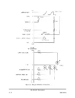
Figure 5.3 HV Bias Measurements


I

L

= Line current

I

L

=

P

V

L

P

F

EFF

P = Average output power
V

L

= Line voltage

P

F

= Power factor (.65 min)

EFF = 0.85

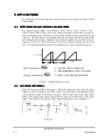
Ex: A 152A operating from 115V - 10% and delivering 1000W average.

I

L

=

1000

(

115

)(

.65

)(

0.85

)

0.9

=

17.5

A

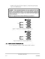
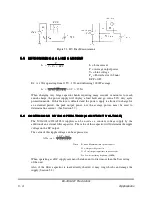
When charging very large capacitor banks requiring many seconds or minutes to reach
end-of-charge, the power supply will display a load fault and go into a 50% duty cycle
protection mode. If this feature is defeated and the power supply is allowed to charge for
an extended period, the peak output power, not the average power, must be used to
determine line current. (See Section 5.7).


  '

 '

 '

 ' 


   (

 (

 (

 (

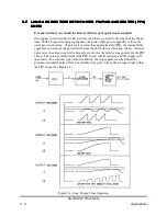
The 500A/102A/152A/202A supplies can be used as a constant voltage supply by the
addition of an external filter capacitor. The value of this capacitor will determine the ripple
voltage on the DC output.

The value of this ripple voltage can be expressed as

:

V

PK

PK

=

1.4

(

Po

max

)

(

Vo

)(

Co

)(

Fs

)

Where : Po max = Maximum outut power in watts

Vo = Output voltage in volts

Co = Total output capacitance in microfarads

Fs = Lowest switching frequency (40KHz)

When operating as a DC supply care must be taken not to draw more than the J/sec rating
of the unit.

Also, if the filter capacitor is inadvertently shorted, it may ring which can damage the
supply (Section 5.2).

83-493-001 Revision G

5 - 4

Applications

Содержание pmn

Страница 1: ...405 ESSEX ROAD NEPTUNE NJ 07753 TEL 732 922 9300 FAX 732 922 9334 INSTRUCTION MANUAL FOR 83 493 001 Revision G MODEL SERIAL NUMBER...

Страница 2: ...23 2 Suffix RFI 2 3 2 23 1 Suffix SYS 2 3 2 23 Options 2 3 2 22 Accessories 2 3 2 21 Note for PFC Units 2 3 2 20 ESD 2 3 2 19 Transient Line Protection 2 3 2 18 Agency Approvals 2 3 2 17 Protection 2...

Страница 3: ...Bias Measurements 5 1 Figure 5 2 Output Current Measurement 5 1 Figure 5 1 Output Voltage Waveform 4 2 Figure 4 1 Eample Of Interface Connection 3 4 Figure 3 3 Output Ground Connection 3 2 Figure 3 2...

Страница 4: ...er A high performance control module precisely regulates the output voltage automatically compensating for line load temperature rep rate variations Normal external fault conditions such as line dropo...

Страница 5: ...kV 40kV All models continuously variable from 0 to 100 of rated output voltage 2 4 1 LINEARITY Linear to within 1 of full scale 2 4 2 ACCURACY 1 of rated Available as fixed Positive or Negative Insula...

Страница 6: ...50 60Hz 200 220 50 60Hz 202A 152A 102A 500A 202A 152A 102A 500A Design Range Nameplate Range Current PFC Non PFC Current No PFC Input Voltage VAC Table 2 2 Input Voltage Chart 0 98 0 65 All models PF...

Страница 7: ...e Inhibit Line the power supply will reach normal operation mode and therefore all other published specifications within 50 ms Detachable 8 feet 2 4 meters HV Cable see Table 2 1 15 pin D plug mating...

Страница 8: ...110 100 to 120 VAC input option for non power factor corrected 152A 1500 J s model NOTE 152A power supply with suffix 110 at 100 120VAC must be operated with internal 20A fuses F1 F2 on inverter bd re...

Страница 9: ...Figure 2 1 Mechanical Dimensions for 500A 102A 152A Outputs up to 6KV for grounding instructions see SECTION 3 6 83 493 001 Revision G 2 5 Specifications...

Страница 10: ...Figure 2 2 Mechanical Dimensions for 500A 102A 152A Outputs from 7KV to 40KV for grounding instructions see SECTION 3 6 83 493 001 Revision G 2 6 Specifications...

Страница 11: ...Figure 2 3 Mechanical Dimensions for 202A Outputs up to 6KV for grounding instructions see SECTION 3 6 83 493 001 Revision G 2 7 Specifications...

Страница 12: ...Figure 2 4 Mechanical Dimensions for 202A Outputs from 7KV to 40KV for grounding instructions see SECTION 3 6 83 493 001 Revision G 2 8 Specifications...

Страница 13: ...hes 101 6mm to minimize stress on the insulation Generally at least 4 inches 101 6mm of clearance should be allowed at the inlet of the power supply and 2 inches 50 8mm at the sides When operating in...

Страница 14: ...fuses F1 and F2 on the Inverter Board replaced by copper bus provided with the supply Use external 30A UL VDC Approved Fuse Circuit Breaker NOTE For Application At less than 10 Hz Please see section 5...

Страница 15: ...educes long term corona effects Keep the minimum HV cable bend radius greater than 4 inches 101 6mm to minimize stress on the insulation Keep the HV cable as distant as possible from the input power a...

Страница 16: ...the supply to the load as shown in Figure 3 3 See Figure 2 1 and 2 2 for grounding cable configuration Figure 3 3 Output Ground Connection 3 6 3 FOR UNITS WITH O P VOLTAGE 6kV The ground connection is...

Страница 17: ...cuit return Also chassis earth ground OUTPUT GND 14 15V regulated Can be used for user programming applications 20mA max OUTPUT 15V 9 11 A 10 to 15V with respect to ground disables the unit Open or gr...

Страница 18: ...Figure 4 1 Eample Of Interface Connection 83 493 001 Revision G 4 2 Operations...

Страница 19: ...protection mode and indicate a LOAD FAULT An overload condition can occur if the INHIBIT signal is missing allowing HV switch to latch up It can also occur if the discharge rep rate is too high to all...

Страница 20: ...roducing an average of 100 J sec The following formulas can be used to determine the average and peak charge rate Peak Charge Rate C OUTPUT LOAD CAPACITOR 1 2 CV2 TC V PROGRAMMED OUTPUT VOLTAGE Averag...

Страница 21: ...ach of the power supplies operate at the same time with the total charge rate equal to the sum of each Sometimes when operating several units in parallel the high total power generates noise which int...

Страница 22: ...where VO is the High Voltage being measured VM R2 R1R2 VO Making a pulsed measurement with an oscilloscope requires a compensated HV probe having a wide bandwidth Simply connecting a DC probe through...

Страница 23: ...age power must be used to determine line current See Section 5 7 The 500A 102A 152A 202A supplies can be used as a constant voltage supply by the addition of an external filter capacitor The value of...

Страница 24: ...apacitors can average the power drawn from the power factor correcting circuit At lower pulse rates the output stage will attempt to draw twice the rated average power fro the PFC circuit The internal...

Страница 25: ...ould be limited to less than five minutes No maintenance is required under normal operating conditions Occasional vacuum or blow out of the chassis may be required when operated in extremely dirty env...

Отзывы: