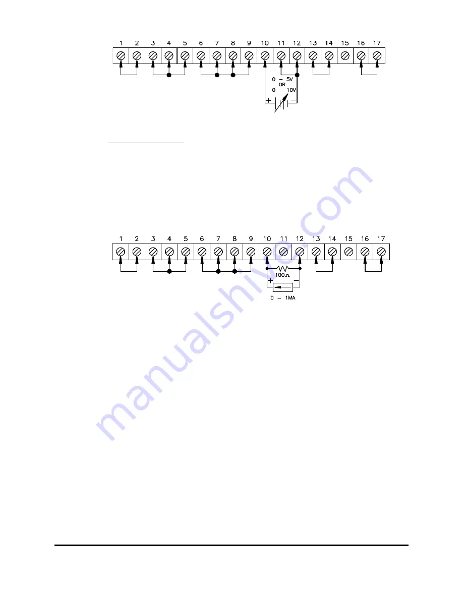
Figure 3.9b: Remote Programming by External Voltage, Current Mode (as per Option)
C.
External DC Current:
A current of 0 to 1mA programs the output from zero to full rated current. Configure the
strapping connections on TB1/J1 as shown on Figure 3.10.
1. Remove the jumper between terminals TB1/J1-9, TB1/J1-10 and TB1/J1-11.
2. Connect a 100 Ohm, 1% 0.5W resistor between TB1/J1-10 and TB1/J1-12.
3. Connect the programming current source between terminals TB1/J1-12 (negative) and
TB1/J1-10 (positive).
Figure 3.10: Remote Programming by External Current, Current Mode
3.4 PARALLEL OPERATION
NOTE:
It is not recommended to operate more than three EMS power supplies in parallel
without thorough evaluation by the user, with counseling from the Engineering Department
of Electronic Measurements, Inc. This will help avoid any failures in the application due
to instability and OVP of the power supplies. The simplest parallel connection is that of
attaching the positive and negative terminals to their respective load points. The
procedure is as follows:
1. Turn on all units (open circuit) and adjust to the appropriate output voltage.
2. Turn supplies off and connect all positive output terminals to the positive side of the load
and all negative supplies to the negative side of the load as in Figure 3.10.
NOTE
: Individual leads connecting the units to the load must be of equal length and
oversized to provide as low an impedance as practical for the high output currents.
3. Set the current controls clockwise.
4. Turn units on one at a time, until the sum of the power supply current capabilities
exceeds the load current drawn.
5. Using the voltage controls, balance each unit voltage for equal output current. Set the
current controls to limit just above running current so that if the output voltage of any
83-473-000 Revision J
3 - 9
Operating Instructions


