Lakos HTX Series Скачать руководство пользователя страница 3

3

Installation Operations and Maintanence

Principle of Operation

Installation Instructions

LAKOS Separators are designed specifically to remove solids from liquids. 

Each model is calculated for use within a prescribed flow range for 

maximum performance and solids removal. Flow rates above and below the 

recommended range may affect such performance. Upon tangential entry, 

the liquid/solids are drawn through internal tangential slots and accelerated 

into the separation chamber where solids heavier than the carrying liquid 

are centrifugally separated and allowed to accumulate in the unit’s collection 

chamber for eventual purging (see Page 5). The liquid (free of separable solids) 

is then drawn to the vortex and up through the separator’s outlet.

1. LAKOS Separators are shipped on skids or in wooden crates. Support legs (22

½° low profiles only) are detached. Lifting Lugs, located on the unit’s side

and/or flanges, are provided for hoisting as necessary.

2. A suitable foundation is necessary to accommodate the LAKOS Separator’s 

weight including liquid. Anchor bolts are recommended in the base of the legs 

(low profile) or skirt (vertical profile).

3. Prior to installation, inspect the inlet/outlet/purge connections for foreign 

objects incurred during shipping/storage.

4. Inlet/outlet pipe connections to the LAKOS Separator should be a straight 

run of at least five pipe diameters to minimize turbulence and enhance 

performance.

5. Proper purge hardware and/or solids-handling equipment is required to flush

separated solids from the separator.

6. All LAKOS Separators operate within a prescribed flow range (Pipe size is not 

a factor in model selection). Use appropriate hardware to match the inlet/outlet 

size.

Содержание HTX Series

Страница 1: ...LS 714B Rev 11 17 1365 N Clovis Avenue Fresno California 93727 559 255 1601 www lakos com HTX HTH SEPARATORS I O MANUAL INSTALLATION OPERATIONS AND MAINTENANCE...

Страница 2: ...ciple of Operation Page 3 Operation Installation Page 3 4 Recommended Piping Page 4 Maintenance Purging Page 5 Maintenance Recommendations Page 6 Trouble Shooting Page 7 9 HTH Flow vs Pressure Loss Ch...

Страница 3: ...LAKOS Separators are shipped on skids or in wooden crates Support legs 22 low profiles only are detached Lifting Lugs located on the unit s side and or flanges are provided for hoisting as necessary...

Страница 4: ...important if the LAKOS Separator is to remain idle in freezing temperatures Drain liquid as necessary to avoid expansion of water to ice and related damage Grooved couplings are not included with the...

Страница 5: ...lected into a separate collection bag Once the bag is full with solids the bag is emptied The bag can be cleaned and reused or simply replaced Consult your LAKOS representative for details on the soli...

Страница 6: ...ole Gasket inspected for leaks and change as necessary Separator Slots should be inspected during facility pipe inspection is required Inspection of slots is recommended when separator performance is...

Страница 7: ...Pressure Actual inlet pressure must be at least 15 psi 1 03 Bar A minimum back pressure of 5 psi 34 Bar must be created at the separator discharge This may be accomplished via process equipment piping...

Страница 8: ...duration proper duration is the time it takes fluid to come out clean in order to pass all accumulated solids through the full length of the purge piping Continuous purge bleed piping must be sized pr...

Страница 9: ...devices should also be properly re sealed after use 10 Air Relief Ports The appropriate air relief ports should be used at start up to expel air from the separator If the separator will be drained pe...

Страница 10: ...4 6 8 1 0 Pressure Loss bar 3 5 7 9 10 15 20 25 50 75 100 150 200 250 500 750 1 000 1 500 2 000 2 500 3 000 Flow Rate m3 hr Pressure Loss psi 3 5 10 12 Flow Rate U S gpm 20 30 40 50 100 10 000 5 000...

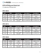
Страница 11: ...DIAMETER FACE GLYCERINE FILLED PART DESC Description 2 Description 3 Description 4 118504 GROMMET STRIP 15 16 x 1 4 EPDM 11 LG 116443 GASKET COUPLING 5 TYPE E GROOVE EPDM 118512 GKT KIT GAUGE 160PSI C...

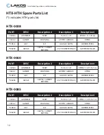
Страница 12: ...AMETER FACE GLYCERINE FILLED PART DESC Description 2 Description 3 Description 4 118504 GROMMET STRIP 15 16 x 1 4 EPDM 19 15 16 LG 106147 GASKET COUPLING 8 TYPE E GROOVE EPDM 118512 GKT KIT GAUGE 160P...

Страница 13: ...AMETER FACE GLYCERINE FILLED PART DESC Description 2 Description 3 Description 4 118504 GROMMET STRIP 15 16 x 1 4 EPDM 27 1 16 LG 106150 GASKET COUPLING 12 TYPE E GROOVE EPDM 106205 GASKET HANDHOLE 4...

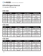
Страница 14: ...INE FILLED PART DESC Description 2 Description 3 Description 4 118504 GROMMET STRIP 15 16 x 1 4 EPDM 50 1 4 LG 119488 GASKET COUPLING 20 TYPE E GROOVE EPDM 106205 GASKET HANDHOLE 4 x 6 NEOPRENE 118512...

Страница 15: ...2 DIAMETER FACE GLYCERINE FILLED PART DESC Description 2 Description 3 Description 4 119685 GASKET ANSI 12 HTX 28 150 1 8 THK NEOPRENE 106205 GASKET HANDHOLE 4 x 6 NEOPRENE 118512 GKT KIT GAUGE 160PSI...

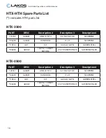
Страница 16: ...NE 106205 GASKET HANDHOLE 4 x 6 NEOPRENE 118512 GKT KIT GAUGE 160PSI CARBON STEEL 106263 GAUGE 160 PSI 1 4 MNPT BOTTOM 2 1 2 DIAMETER FACE GLYCERINE FILLED PART DESC Description 2 Description 3 Descri...

Страница 17: ...Order _______________________________________ Purchase Date ______________________________________ Distributor _________________________________________ System Flow _____________________ Separator De...

Отзывы: