


Lake Shore Model 331 Temperature Controller User’s Manual
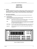
3.6
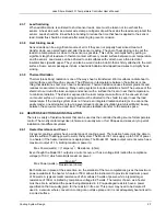
THERMOCOUPLE SENSOR INPUTS (Model 331X-TX Only)
The information in this paragraph is for a Model 331 configured at the factory with one or two
thermocouple sensor inputs; being Model 331X-T1 or T2. Sensor connection is important when using
thermocouples because the measured signal is small. Many measurement errors can be avoided with
proper sensor installation.
CAUTION:
Do not leave thermocouple inputs unconnected. Short inputs when not in use.
3.6.1
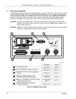
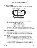
Sensor Input Terminals
Attach sensor leads to the screws on the off-white ceramic terminal blocks. Each block has two screw
terminals; one positive (on the I+
/
V+ side of the connector), one negative (on the I–
/
V– side of the
connector). See Figure 3-4.
The current and voltage references silkscreened on the back panel are for the diode/resistor
connectors. For thermocouples, the positive (+) wire goes to the left-side terminal and the
negative (–) wire to the right-side terminal. Remove all insulation then tighten the screws on the
thermocouple wires. Keep the ceramic terminal blocks away from heat sources including sunlight
and shield them from fans or room drafts.
I+
I
V
V+
!
Therm
o
c
o
u
p
le
P
o
sitive Termin
a
l
Therm
o
c
o
u
p
le
Ne
ga
tive Termin
a
l
Common Thermocouple Polarities
Positive (+)
Negative (–)
Type K (Nickel-Chromium vs. Nickel-Aluminum)
Chromel (YEL)
Alumel (RED)
Type E (Nickel-Chromium vs. Copper-Nickel)
Chromel (PUR)
Constantan (RED)
Type T (Copper vs. Copper-Nickel)
Copper (BLU)
Constantan (RED)
Chromel-AuFe 0.03%
Chromel
Gold
Chromel-AuFe 0.07%
Chromel
Gold
Figure 3-4. Thermocouple Input Definition and Common Connector Polarities
3.6.2 Thermocouple
Installation
Thermocouples are commonly used in high-temperature applications. Cryogenic use of
thermocouples offers some unique challenges. A general installation guideline is provided in
Paragraph 2.3. Consider the following when using thermocouples at low temperatures:
• Thermocouple wire is generally more thermally conductive than other sensor lead wire. Smaller
gauge wire and more heat sinking may be needed to prevent leads from heating the sample.
• Attaching lead wires and passing through vacuum tight connectors are often necessary in
cryogenic systems. Remember, the thermocouple wire
is
the sensor; any time it joins or contacts
other metal, there is potential for error.
• Temperature verification and calibration of room temperature compensation is difficult after the
sensor is installed. When possible, keep a piece of scrap wire from each installation for future use.
3.6.3
Grounding and Shielding
For lowest measurement noise, do not ground thermocouple sensors. The instrument usually
operates with more noise if one of the thermocouples is grounded. Grounding both thermocouples is
not recommended. The instrument does not offer a shield connection on the terminal block. Twisting
the thermocouple wires helps reject noise. If shielding is necessary, extend the shield from the oven
or cryostat to cover the thermocouple wire, but do not attach the shield to the instrument.
Installation
3-7


