WB50NBT
Quick Start Guide
Embedded Wireless Solutions Support Center:
http://ews-support.lairdtech.com
www.lairdtech.com/wi-fi
5
© Copyright 2016 Laird. All Rights Reserved
Americas: +1-800-492-2320
Europe: +44-1628-858-940
Hong Kong: +852 2923 0600
Additional Required Equipment
Qty.
Item
1
Small Philips head jeweler’s screw driver
1
USB to RS232 DB9/DB25 cable
1
CAT 5 e cable (optional)
1
USB A to USB B cable (optional)
Hardware Installation and Configuration
To assemble the WB50NBT evaluation kit, follow these steps:
Note: To prevent damage, you must connect the U.FL ultra-micro coax cables to the connectors on the
WB50NBT prior to fitting the WB50NBT to the BB40NBT evaluation board.
1.
Using the four nuts provided, attach the four standoffs to the underside corners of the BB40NBT board.
2.
Before fitting the WB50NBT to the BB40NBT evaluation board, turn the WB50NBT so that the 120 way is
on the underside of the board.
3.
Connect the dual band antennas with an SMA connector to each of the AUX. ANT and MAIN ANTENNA
SMA connectors on the top side of the BB40BNT board.
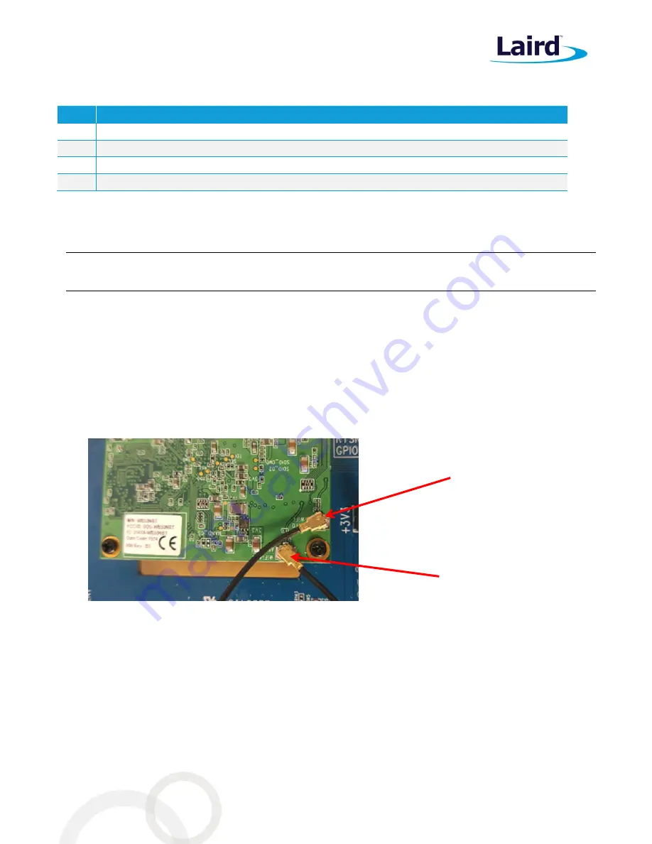
shows the location of the Wi-Fi and Wi-Fi
/Bluetooth antennas. This information is also available on the silk screen on the WB50NBT.
4.
Plug the WB50NBT module into the 120-pin high-density Kyocera connector situated near the central
aperture on the BB40NBT breakout board making sure to feed the two SMA connectors on the ends of the
U.FL coax cables through the aperture in the BB40NBT breakout board.
Figure 1: Location of the Wi-Fi and Bluetooth U.FL connectors on the SDB-WB50NBT
5.
Using the small Philips head jeweler’s screw driver, secure the WB50NBT to the BB40NBT board using the
three small Philips screws.
6.
Feed the SMA connector connected to the ANT0 WI-FI to the aperture marked MAIN ANTENNA on the
BB40NBT board and, using the provided nuts and washers, secure the SMA connector to the BB40NBT
board.
7.
Repeat for the ANT1 Wi-Fi and BT SMA, this time to the aperture marked AUX. ANT on the BB40NBT
board.
You can power the BB40NBT from mains power using the 12v power pack provided.
jack and the power switch. Ensure the power switch is set to Off.
Wi-Fi only antenna
cable connected to
U.FL connector
Wi-Fi and BT antenna cable
connected to U.FL connector
Содержание WB50NBT
Страница 1: ...A Quick Start Guide WB50NBT Version 1 1...


