background image

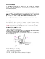
4,  Insert  lock  rod  A  (Fig.16)  into  handwheel  hole.  Hold  the  rod  and  tighten  the  faceplate 
with faceplate wrench. 
5

There  is  a  set  screw  on  face  plate.  Please  tighten  it  when  you  work  with  the  lathe  in 

reverse rotation. 


  Fig. 16 

 
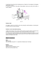
Tailstock Quill 
 

The tailstock quill can be turned in and out by turning the quill handwheel. A locking lever 
is used for secure the quill in position. 


Tailstock centers Installation/removing 
 

1, Make sure the taper of the center and the quill hole are clean and free of debris. Then 
push the center into the quill hole.The taper contact will hold the center securely.   
2, To remove the center from tailstock, loosen the tailstock locking lever and move the quill 
out by turning the quill hand wheel until the quill end is almost inside the tailstock, then the 
center can be taken out by hand. 


MAINTENANCE 

 
Daily:   

Clean off dust; 
Clean and apply rust-proof oil    on spindle and tailstock quill, bed ways.   


Monthly: 

Check belt tension; 
Replace belt if it is damaged or worn; 
Clean off dust from pulleys if any. 


Содержание Revo 2036

Страница 1: ...072 Alton Parkway Irvine California 92606 Ph 800 234 1976 www lagunatools com Model Numbers MLA Revo 20 0180 MLA Revo 24 0180 2017 Laguna Tools Inc LAGUNA and the LAGUNA Logo are the registered tradem...

Страница 2: ......

Страница 3: ...istributor Read carefully before operating the machine 1 Keep the working area clean and be sure adequate lighting is available 2 Do not wear loose clothing gloves bracelets necklaces or ornaments Wea...

Страница 4: ...empted by others Laguna Tools Inc is not responsible for additional tools or modifications sold or performed other than from by Laguna Tools Inc on any Laguna Tools Inc machine Warranty maybe voided u...

Страница 5: ...00 RPM Digital wide angle speed readout with blue backlight Extraordinarily high torque at low speeds for easy working on large workpiece Oversized alloy spindle supported by three precision bearings...

Страница 6: ...Identifications...

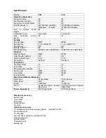
Страница 7: ...h Tailstock 3 8 3 8 Tailstock Quill Travel 4 1 2 4 1 2 Swing away Optional Standard Accessories Tool Rest Width 14 14 Face Plate 3 3 Swing away Bed Length 12 12 Spur Center MT 2 MT 2 Live Center MT 2...

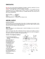
Страница 8: ...electrical box and motor away from direct sun shine Plenty of space around the lathe is good for operations and maintenances Unpacking Report any damage to your shipping agent or dealer immediately a...

Страница 9: ...tach the legs to the bed by using 12mm hex head bolts A with washer B Firmly tighten the bolts 3 After firmly securing the legs to the lathe carefully lower the lathe onto the floor 4 Adjust the level...

Страница 10: ...n be aligned with the front comparator bracket Use two 12mm head cap screws to secure rear comparator bracket to the tailstock Spindle Shield Optional Fig 5 1 Lift up the spring pin B and insert the s...

Страница 11: ...d for convenience operation Fig 8 12 Swing away Extension Bed Standard for T 60 Optional for T 50 12 swing away bed is standard for T60 lathe pre installed before delivery If you purchase the Swing Aw...

Страница 12: ...the bed and extension bed with head cap screws spring washers and flat washer Fig 11 Do not tighten head cap screws at this moment Use alan wrench to tun the set screws until it hit beds Then firmly t...

Страница 13: ...and the belt runs smooth 6 Pushing the tension release lever properly and tighten the lock lever A Note The best belt tension should be that when pressing belt on the middle by one finger the bellt d...

Страница 14: ...and tailstock can slide along the bed Loosen the locking lever and move the Headstock or Tailstock to a desired place Tighten the lever firmly after adjustment CAUTION Always Unplug the lathe from the...

Страница 15: ...oving 1 Make sure the taper of the center and the quill hole are clean and free of debris Then push the center into the quill hole The taper contact will hold the center securely 2 To remove the cente...

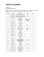
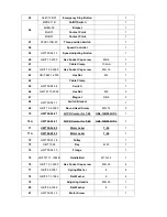
Страница 16: ...HWT50 01 31 Lock Shaft 2 6 HWT50 01 32 Clamp Block 3 7 GB T 889 1 2000 Lock Nut M20 3 8 HWT50 01 33 Position Block 3 9 GB T70 2 2000 Round Head screw M6 16 11 10 GB T117 Taper Pin 6 20 8 11 HWT50 01 1...

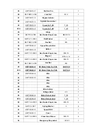
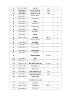
Страница 17: ...Cap screw M8 16 37 Magnet D15 5 4 2 38 GB T 70 3 2000 Hex Socket Cap screw M4 12 2 39 GB T 889 1 2000 Hex Nut M4 2 40 HWT50 04 02 DC Motor Driver for T 50 2HP T 50 1 40A HWT60 04 02 DC Motor Driver fo...

Страница 18: ...66 GB T 6173 2000 Hex Nut M8 2 67 Magnet D8 5 2 68 HWT50 04 11 Switch Bracket 1 69 GB T 70 2 2000 Round Head Screw M5 12 2 70 HWT50 04 01 2HP DC motor for T 60 HBL 124IM 2HP L 1 70A HWT60 04 01 3HP D...

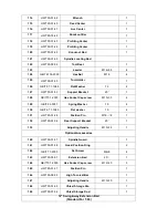
Страница 19: ...le M10 45 1 94 HWT50 02 08 Lock Block 1 95 HWT50 03 01 Tool post Base 1 96 HWT50 03 03 Lock Handle 1 97 HWT50 03 06 Brass Sleeve 1 98 HWT50 03 04 Lock Shaft 1 99 Adjusting Handle M10 25 1 100 HWT50 01...

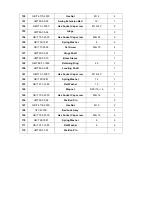
Страница 20: ...70 1 2000 Hex Socket Cap screw M10 30 4 129 GB T 93 1987 Spring Washer 10 4 130 GB T 97 1 1985 Flat washer 10 4 131 HWT50 01 28 Position Pin M12 8 1 132 HWT50 01 04 Rear Support Bracket 20 1 133 Adjus...

Страница 21: ...Sleeve 1 159 GB T 893 1 1986 Retaining Ring 25 1 160 HWT50 05 08 Locating Shaft 1 161 GB T70 1 2000 Hex Socket Cap screw M12 20 1 162 GB T 93 1987 Spring Washer 12 1 163 GB T 97 1 1985 Flat Washer 12...

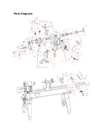
Страница 22: ...Parts Diagrams...

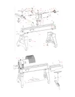
Страница 23: ......

Страница 24: ...ations subject to change Machines may be shown with optional accessories 2017 Laguna Tools Inc LAGUNA and the LAGUNA Logo are the registered trademarks of Laguna Tools Inc All rights reserved 2072 Alt...

Отзывы: