background image


45 


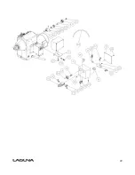
Optional 20" Bed Extension with Riser Block and Tool Rest Extension 

Index 

Part Number 

Item Description 

Specification 

Qty

PLAREVO1836-301  20" Bed Extension 


PLAREVO1836-147  Stop Bolt 


PLAREVO1836-195  Socket Head Cap Screw 

3/8-16UNCx1" 

PLAREVO1836-304  Riser Block 


PLAREVO1836-305  Riser Block Locking Handle 


PLAREVO1836-306  Riser Block Adjusting Plate 


PLAREVO1836-119  Clamp 


PLAREVO1836-114  Clamp Bolt 


PLAREVO1836-115  Sleeve 


10 

PLAREVO1836-116  Rubber Sleeve 


11 

PLAREVO1836-1145  Cap 


12 

MPAREVO1836-189  E-Ring 

E15 

13 

PLAREVO1836-185  Key 

6x6x30 

14 

PLAREVO1836-194  Socket Head Button Screw 

M8x20 

15 

PLAREVO1836-315  Socket Head Button Screw 

M8x50 

16 

PLAREVO1836-199  Set Screw 

M8x6 

17 

PLAREVO1836-1110  Nylon Insert Lock Nut 

M18x2.5 

18 

PLAREVO1836-1114  Lock Washer 

5/16" 

19 

PLAREVO1836-319  Tool rest Extension 


20 

PLAREVO1836-320  Socket Head Button Screw 

3/8-16UNCx1-1/4" 

21 

PLAREVO1836-1115  Lock Washer 

3/8" 


Содержание REVO 18

Страница 1: ......

Страница 2: ...nes and CNC routers and Plasma machines Through my hands on experience I work hard to make our machines better I strive to give you machines that inspire you to create works of art machines that are a joy to run and work on machines that encourage your performance Today we offer high performance machines with innovative solutions that meet the needs of Craftsman and their ever evolving craft I sta...

Страница 3: ...heet 10 Receiving your machine 11 Introduction to your machine 11 Parts of the machine 11 What you will receive with the machine 16 Where to locate your machine 17 Unpacking your machine 18 Assembly and setup 19 Maintenance 30 Troubleshooting 33 Electrical drawing 35 Exploded view drawings 36 ...

Страница 4: ...t un nœud g U liser la vitesse la plus lente au démarrage d une nouvelle pièce 1 CONSERVEZ TOUS LES DISPOSITIFS DE PROTECTION EN PLACE et en bon état de fonc onnement 2 ENLEVEZ LES CLÉS ET OUTILS Prenez l habitude de vérifier si les clés et autres ou ls ne sont pas trop près de la machine avant de la démarrer 3 CONSERVEZ LA SURFACE DE TRAVAIL PROPRE ET LIBRE D ENTRAVES Les endroits encombrés augmen...

Страница 5: ...e receptacles that accept the tool s plug Repair or replace damaged or worn cord immediately 2 Grounded cord connected tools intended for use on a supply circuit having a nominal rating less than 150 volts This tool is intended for use on a circuit that has an outlet that looks like the one illustrated in Sketch A in Fig 1 The tool has a grounding plug that looks like the plug illustrated in Sketc...

Страница 6: ...Fig 1 ...

Страница 7: ...he control panel We have supplied two concepts for locking the panel see below The cover can be made from wood or plastic First push down the emergency stop Then lock the cover together by putting padlocks not included on the two handles on the control panel To safeguard your machine from unauthorized operation and accidental starting by young children the use of padlocks is strongly recommended ...

Страница 8: ...8 Wooden safety cover Padlocks Emergency stop switch Plastic safety cover Padlocks ...

Страница 9: ...thers Laguna Tools Inc is not responsible for additional tools or modifications sold or performed other than from by Laguna Tools Inc on any Laguna Tools Inc woodworking machine Warranty may be voided upon the addition of such noted tools and or modifications determined on a case by case basis Normal user alignment adjustment tuning and machine settings are not covered by this warranty It is the r...

Страница 10: ... 60hz single phase input 3 phase output Recommended breaker size 15 amp 15 amp Swing over bed 18 457mm 18 457mm Swing over banjo 13 5 343mm 13 5 343mm Outboard swing max 32 813mm 32 813mm Distance between centers 36 914mm 36 914mm Floor to spindle center 41 5 1054mm 41 5 1054mm Floor to bed height 32 5 with pads 826mm 32 5 with pads 826mm Floor space W60 D26 H47 1524mm 660mm 1194mm W60 D26 H47 152...

Страница 11: ...deavours to test machines prior to shipping to customers as movement can take place during transportation It must be noted that additional machine movement can take place between Laguna Tools and the end user and some adjustments may have to be undertaken by the customer These adjustments are covered in the various sections of this manual Introduction to lathes This machine is designed to give you...

Страница 12: ...ication There is a plate at the back of the machine listing all the manufacturing data including the serial number model etc Lathe Bed The bed is a machined heavy steel welded construction Underside of lathe bed ...

Страница 13: ...it is very stable The legs are supplied with adjustable feet to allow the machine to be leveled Legs with adjustable feet assembled Head stock The head stock is cast iron and houses the variable speed control and motor The Spindle can be locked in 14 36 and 48 positions Headstock removed from the bed Headstock attached to bed ...

Страница 14: ... to any position on the lathe bed and locked to suit the job at hand Tool rest The tool rest can be moved to any position on the lathe bed and locked to suit the job at hand The tool rest has a tall profile to allow the bowl turner to turn steep angles The leading edge is made from 6mm hardened steel Tailstock viewed from the back Tailstock viewed from the front Tool rest assembled to the bed Tool...

Страница 15: ...e spindle A power cord with 220V plug is provided 110V The electrical control system VFD is housed at the back of the head stock The VFD converts single phase 110v to three phase There is a speed readout at the front of the lathe with controls to fine adjust the RPM of the spindle A power cord with 110V plug is provided Tool storage A tool storage bracket which can be mounted on either leg VFD wit...

Страница 16: ...16 What you will receive with the lathe Head stock Tool rest Tail stock Drive live center storage Tool storage Leg Bed Banjo Adjustable feet Leg ...

Страница 17: ... a few guidelines 1 There should be sufficient area at the front of the machine to allow you to work on it comfortably 2 There should be sufficient area at the back of the machine to allow access for adjustments and maintenance to be conducted 3 Adequate lighting The better the lighting the more accurately and safely you will be able to work 4 Solid floor You should select a solid flat floor prefe...

Страница 18: ... COULD CAUSE INJURY Lathe in packaging Leg Parts of the lathe Second leg Top packaging removed 2 Open the box and remove the parts sent with the lathe including the first leg Note The legs are heavy and caution must be exercised They are cast iron and if dropped they will break 3 Remove the top packaging and remove the second leg 4 Remove the lathe bed It is recommended that it be lifted with a ho...

Страница 19: ... the bed of the machine Note It is recommended that the head stock tool rest and tailstock be removed from the bed of the lathe to ease assembly Covered later in the manual Assembling the legs to the bed of the lathe There is a stop at both ends of the bed The stop is a safety feature that makes it impossible for the headstock or tailstock to slide off the end of the bed Remove the stops and loose...

Страница 20: ...sition and one to fit the fixing screws Note If you have any doubt about the described procedure seek professional assistance Do not attempt any procedure that you feel is unsafe or that you do not have the physical capability of achieving Fit the 4 leveling feet to the lathe legs with the lock nut on the underside of the leg Once both legs have been fitted turn the assembly up to the correct posi...

Страница 21: ...nto the bed of the lathe and fit the stops Note If you have any doubt about the described procedure seek professional assistance Do not attempt any procedure that you feel is unsafe or that you do not have the physical capability of achieving Assembled lathe ...

Страница 22: ... that the washer recess fits into the slot in the bed Fit the banjo onto the bed with the bolt through the washer and assemble the nut onto the thread Adjust the nut so that the clamp handle locks the banjo with approximately 30 degree of movement Tool rest unassembled Washer Washer assembled in position Tool rest clamp handle Banjo clamp handle ...

Страница 23: ...It is recommended that you use a 15 amp main breaker Note A qualified electrician must carry out the installation Cleaning the machine Remove the rust protection grease with WD 40 or a similar solvent It is important that you remove all the grease and re lubricate with a Teflon based lubricant Teflon has a lower tendency to attract sawdust and cause clogging Tail stock knob Tail stock handle Elect...

Страница 24: ...s far back as possible and this will eject the center Fitting the drive center into the head stock To remove the face plate from the head stock spindle insert the removal tool into the hole in the face plate large diameter Lock the spindle with the lathe spindle lock and unlock the face plate by rotating it Take care not to drop the faceplate onto the bed of the lathe Note The face plate has a lef...

Страница 25: ...rocedure described earlier Lathe controls Emergency stop button The emergency stop button will lock in the OFF position when fully depressed To reset it twist clockwise and it will pop out Forward reverse switch The forward reverse switch selects the direction of the rotation of the spindle The forward reverse switch must only be used once the spindle has come to a complete stop Start Stop buttons...

Страница 26: ...allows the head stock to be released and moved to any position on the lathe bed It is located at the back of the head stock Emergency stop button Start stop buttons Speed display Forward reverse switch Variable speed adjustment knob Head stock clamp lever ...

Страница 27: ...s as follows 1 Disconnect the electric supply to the lathe 2 Open the pulley cover 3 Loosen the motor lock handle and lift the motor to the highest position with the motor adjustment handle then lock the motor lock handle 4 Move the drive belt to the required set of pulleys 5 Loosen the motor lock handle and with the motor adjustment handle tension the drive belt then lock the motor lock handle Th...

Страница 28: ...nobs Try the plunger in a few different holes to check that it inserts and removes smoothly The indexing plunger is spring loaded and this is used only to temporarily align the plunger in the selected hole To fix the plunger in a selected hole it must be attached to the housing by screwing into the clamped position There is a hole selection indicator that allows you to view which hole in a selecte...

Страница 29: ...29 Indexing holes Clamping knobs Hole selection indicator Hole selection Indexing plunger Indexing plunger engaged Indexing plunger disengaged ...

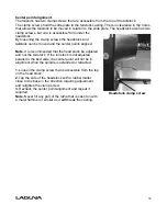
Страница 30: ...l none painted surfaces will rust if not protected It is recommended that they be protected by applying wax or a Teflon based lubricant to them Center point alignment and slide clearance adjustment The center point alignment and slide clearance are adjusted at the factory and no adjustment should be required Should movement or wear have taken place the following adjustment procedure should be cond...

Страница 31: ...as above should be conducted on the head stock should it be required Note It is very unlikely that the headstock will require adjustment as it is not moved as often as the tailstock so has less tendency s for ware Adjustment slot View under the tailstock Adjustment slot View under headstock Clamp screw Adjusting screw ...

Страница 32: ... points aligned Note It is recommended that the head stock be adjusted and not the tail stock If the tail stock is not adjusted parallel to the bed slide the center point will not be in alignment when the spindle is extended or retracted 1 Loosen the clamp screw that is accessible from the top on the head stock 2 Tap the side of the headstock with a rubber mallet close to the base in the direction...

Страница 33: ...turn the spindle by hand If the spindle will not turn check the reason for jamming 2 Capacitor faulty Replace the capacitor 3 Motor faulty Replace the motor 4 Power line overloaded Correct overloaded condition 5 Low voltage Correct low voltage condition Motor overheats The motor is designed to run hot but should it overheat it has an internal thermal overload protector that will shut it down until...

Страница 34: ...e floor Re level the machine ensuring that it has no movement 2 Damaged drive belt Replace the belt 3 Job is not balanced Change to slower speed and or balance the job 4 Damaged pulley Replace the pulley 5 Worn spindle bearing Replace the bearing ...

Страница 35: ...35 Electrical drawing ...

Страница 36: ...36 Exploded view drawings and parts list ...

Страница 37: ...37 ...

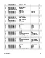
Страница 38: ...VO1836 114 Clamp Bolt 3 15 PLAREVO1836 115 Sleeve 2 16 PLAREVO1836 116 Rubber Sleeve 2 17 PLAREVO1836 117 Knob 1 18 PLAREVO1836 118 Headstock Adjusting Plate 1 19 PLAREVO1836 119 Clamp 2 20 PLAREVO1836 120 Lock Handle 1 21 PLAREVO1836 121 Control Panel 1 22 PLAREVO1836 122 Handwheel 1 23 PLAREVO1836 123 Motor 2HP 1 PLAREVO1836 110 150 123 Motor 1 5HP 1 24 PLAREVO1836 124 Spur Center 1 25 PLAREVO18...

Страница 39: ...y 1 51 PLAREVO1836 151 Knockout Rod 1 52 PLAREVO1836 152 Braking Resistor Cord 1 53 PLAREVO1836 153 Lock Handle 1 54 PLAREVO1836 154 Control Box 1 55 PLAREVO1836 155 Control Cord 1 56 PLAREVO1836 156 Tailstock Tool Caddy 1 57 PLAREVO1836 157 Hex Cap Screw M6x6 4 58 PLAREVO1836 158 Door Hinge 1 59 PLAREVO1836 159 Speed Knob 1 60 PLAREVO1836 160 Rubber Sleeve 2 61 PLAREVO1836 161 Rubber Bushing 1 62...

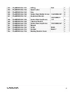
Страница 40: ...REVO1836 186 Key 8x7x25 1 87 PLAREVO1836 187 Key 8x7x60 1 88 PLAREVO1836 188 E Ring E19 2 89 PLAREVO1836 189 E Ring E15 4 90 PLAREVO1836 190 E Ring E5 1 91 PLAREVO1836 191 C Ring R22 1 92 PLAREVO1836 192 Socket Head Cap Screw 1 4 20UNCx1 1 93 PLAREVO1836 193 Hex Cap Screw 3 8 16UNCx1 2 1 94 PLAREVO1836 194 Socket Head Button Screw M8x20 2 95 PLAREVO1836 195 Socket Head Cap Screw 3 8 16UNCx1 1 96 P...

Страница 41: ...PLAREVO1836 1121 Socket Head Button Screw M8x45 1 122 PLAREVO1836 1122 Socket Head Cap Screw 5 16 18UNCx1 2 3 123 PLAREVO1836 1123 Poly V Belt PJ8 190 1 124 PLAREVO1836 1124 Set Screw 3 16 24UNCx3 16 2 125 PLAREVO1836 1125 Set Screw 5 16 18UNCx1 4 1 126 PLAREVO1836 1126 Socket Head Button Screw 3 8 16UNCx5 8 2 127 PLAREVO1836 1127 Screw M3x12 2 128 PLAREVO1836 1128 Spacer 2 129 PLAREVO1836 1129 Ha...

Страница 42: ...x3 8 8 147 PLAREVO1836 1147 Headstock Bracket 1 148 PLAREVO1836 1148 Socket Head Cap Screw 3 8 16UNCx1 1 4 2 149 PLAREVO1836 1149 Tailstock Bracket 1 150 PLAREVO1836 1150 Socket Head Cap Screw 3 8 16UNCx3 4 2 151 PLAREVO1836 1151 Magnet 1 152 PLAREVO1836 1152 Screw M4x6 2 153 PLAREVO1836 1153 Hex Nut M4x0 7 1 154 PLAREVO1836 1154 Braking Resistor Cover 1 ...

Страница 43: ...onal Headstock Guard Index Part Number Item Description Specification Qty 1 PLAREVO1836 201 Plunger 1 2 PLAREVO1836 202 Retaining Collar 2 3 PLAREVO1836 203 Guard 1 4 PLAREVO1836 204 Set Screw 1 4 20UNCx1 4 2 ...

Страница 44: ...44 ...

Страница 45: ...AREVO1836 119 Clamp 1 8 PLAREVO1836 114 Clamp Bolt 1 9 PLAREVO1836 115 Sleeve 1 10 PLAREVO1836 116 Rubber Sleeve 1 11 PLAREVO1836 1145 Cap 1 12 MPAREVO1836 189 E Ring E15 4 13 PLAREVO1836 185 Key 6x6x30 1 14 PLAREVO1836 194 Socket Head Button Screw M8x20 1 15 PLAREVO1836 315 Socket Head Button Screw M8x50 1 16 PLAREVO1836 199 Set Screw M8x6 2 17 PLAREVO1836 1110 Nylon Insert Lock Nut M18x2 5 1 18 ...

Страница 46: ...1 2 PLAREVO1836 402 Draw Latch Assembly 1 3 PLAREVO1836 403 Hinge 1 4 PLAREVO1836 404 Pin 2 5 PLAREVO1836 147 Stop Bolt 1 6 PLAREVO1836 406 Socket Head Cap Screw M6x12 4 7 PLAREVO1836 407 Phillips Flat Head Screw M5x12 5 8 PLAREVO1836 320 Socket Head Button Screw 3 8 16UNCx1 1 4 2 9 PLAREVO1836 409 Set Screw 3 16 24UNCx3 8 4 ...

Страница 47: ...47 Optional Comparator Index Part Number Item Description Specification Qty 1 PLAREVO1836 501 Center 2 2 PLAREVO1836 502 Lock Handle 2 ...

Страница 48: ...48 Optional Industrial Flood Light Index Part Number Item Description Specification Qty 1 PLAREVO1836 601 Work Light 1 2 PLAREVO1836 602 Screw M4x15 4 ...

Страница 49: ...49 ...

Страница 50: ... 813 Quick Release Fitting 1 14 PLAREVO1836 814 Pressure Vacuum Gauge 1 15 PLAREVO1836 815 Gauge Fitting 1 16 PLAREVO1836 816 Vacuum Switch 1 17 PLAREVO1836 817 H Type Fitting 1 18 PLAREVO1836 818 Flat Type Silencer 1 19 PLAREVO1836 819 T Type Fitting 1 20 PLAREVO1836 820 Straight Fitting Female 1 21 PLAREVO1836 821 Ball Bearing 6003ZZ 1 22 PLAREVO1836 822 Screw M4x30 2 23 PLAREVO1836 823 Air Hose...

Страница 51: ......

Страница 52: ...836 909 Spacer 4 10 PLAREVO1836 910 Cylinder 2 11 PLAREVO1836 911 Nylon Insert Lock Nut M10x1 5 4 12 PLAREVO1836 912 Support Bracket 2 13 PLAREVO1836 913 Bushing 2 14 PLAREVO1836 914 Socket Head Cap Screw M10x35mm 4 15 PLAREVO1836 915 Connecting rod 2 16 PLAREVO1836 916 Bushing 2 17 PLAREVO1836 917 Foot Brake 2 18 PLAREVO1836 918 Socket Head Cap Screw M8X30mm 2 19 PLAREVO1836 919 Bushing 2 20 PLAR...

Страница 53: ...3 Riser Blocks 2 2 PLAREVO1836 702 Socket Head Cap Screw 3 8 16UNCx3 1 2 4 3 PLAREVO1836 1115 Lock Washer 3 8 8 4 PLAREVO1836 1146 Socket Head Button Screw 1 4 20UNCx3 8 4 5 PLAREVO1836 705 Support Bracket 2 6 PLAREVO1836 706 Support Bracket 2 7 PLAREVO1836 707 Socket Head Cap Screw 3 8 16UNCx3 4 8 ...

Страница 54: ......

Страница 55: ......

Страница 56: ...cations subject to change Machines may be shown with optional accessories 2017 Laguna Tools Inc LAGUNA and the LAGUNA Logo are the registered trademarks of Laguna Tools Inc All rights reserved 2072 Alton Parkway Irvine CA 92606 Ph 800 234 1976 www lagunatools com ...

Отзывы: