background image


60 

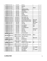
PBAND1412-175-2-27 

1412-227 

Lower Blade Guard 


PBAND1412-175-2-28 

1412-228 

Screw 

1/4"-20x3/4" 

PBAND1412-175-2-29 

1412-229 

Plate 


PBAND1412-175-2-30 

1412-132 

Hex Nut 

1/4”-20 

PBAND1412-175-2-31 

1412-133 

Door Stud 


PBAND1412-175-2-32 

1412-232 

Flat Washer 

1/4” 

PBAND1412-175-2-33 

1412-233 

Nylon Inserted Lock Nut 

1/4”-20 

PBAND1412-175-2-34 

1412-146 

Lock Knob 


PBAND1412-175-2-35 

1412-145 

Screw 

1/4"-20x3/4" 

PBAND1412-175-2-36 

1412-236 

Plate 


PBAND1412-175-2-37 

1412-237 

Screw 

#10-24×3/8" 

PBAND1412-175-2-38 

1412-238 

Strain Relief 

6N-4 

MBAND14BX110-175-2-

39 

14BX110-175-239 

Motor Cord 


MBAND14BX110-175-2-

40 

14BX110-175-240 

Power Cord(110V) 


MBAND14BX220-250-2-

40 

14BX220-250-240 

Power Cord(220V) 


PBAND1412-175-2-41 

1412-241 

Hex Cap Screw 

3/8"-16x1" 

PBAND1412-175-2-42 

1412-242 

Flat Washer 

3/8" 

PBAND1412-175-2-43 

1412-108 

Lock Washer 

3/8" 

PBAND1412-175-2-44 

1412-244 

Hex Nut 

M14x1.5 

PBAND1412-175-2-45 

1412-245 

Motor(110V) 


MBAND14BX220-250-2-

45 

14BX220-250-245 

Motor(220V) 


PBAND1412-175-2-45-1 

1412-245MF 

Motor Fan (not shown) 


PBAND1412-175-2-45-2 

1412-245MFC 

Motor Fan Cover (not shown) 


PBAND1412-175-2-45-3 

1412-245JB 

Junction Box (not shown) 


PBAND1412-175-2-45-4 

1412-245JBC 

Junction Box Cover (not 
shown) 


PBAND1412-175-2-46 

1412-246 

Spindle Holder 


PBAND1412-175-2-47 

1412-247 

Adjusting Screw 


PBAND1412-175-2-48 

1412-248 

Hex Cap Screw 

3/8"-16×1-3/4" 

PBAND1412-175-2-49 

1412-249 

Flat Washer 

M14 

MBAND14BX110-175-2-

50 

14BX110-175-250 

Switch Cover 


MBAND14BX110-175-2-

51 

14BX110-175-251 

Hex Nut 

M6x1.0 


Содержание MBAND14BX110-175

Страница 1: ...800 234 1976 www lagunatools com Part No MBAND14BX110 175 LT14BX Bandsaw 110V 1 75HP 13 Resaw Part No MBAND14BX220 250 LT14BX Bandsaw 220V 2 5HP 13 Resaw 2017 Laguna Tools Inc LAGUNA and the LAGUNA L...

Страница 2: ......

Страница 3: ...3...

Страница 4: ...4...

Страница 5: ...f the electric cord or plug is necessary do not connect the equipment grounding conductor to a live terminal Check with a qualified electrician or service personnel if the grounding instructions are n...

Страница 6: ...tch D The tool has a grounding plug that looks like the plug illustrated in Sketch D Make sure the tool is connected to an outlet having the same configuration as the plug No adapter is available or s...

Страница 7: ...concepts for locking the panel see below The cover can be made from wood or plastic First push down the emergency stop Then lock the cover together by putting padlocks not included on the two handles...

Страница 8: ...n 10 Receiving your machine 11 Introduction to Bandsaws 11 What you will receive with your Bandsaw 12 Parts of the Bandsaw 14 Where to locate your machine 18 Unpacking your machine 18 Assembly and set...

Страница 9: ...empted by others Laguna Tools Inc is not responsible for additional tools or modifications sold or performed other than from by Laguna Tools Inc on any Laguna Tools Inc machine Warranty maybe voided u...

Страница 10: ...a ceramic Laguna ceramic Height 70 1 2 1 790mm 70 1 2 1 790mm Machine Dimensions W x D Base Footprint 29 3 4 x 26 7 8 755mm x 683mm 22 11 16 x 17 9 16 576mmx446mm 29 3 4 x 28 1 16 755mm x 713mm 22 11...

Страница 11: ...om country to country Receiving your machine It is probable that your machine will be delivered by a third party Before you unpack your new machine you will need to first inspect the packing invoice a...

Страница 12: ...ept for special cuts that the wood will be thrown back at the operator which is called a kickback There is always danger of kickback when a circular saw is being used For safety reasons many woodworke...

Страница 13: ...13 Fence guide bar Table ratchet handles washers Rubber feet and fixings Table Fence guide bar attachment parts T bar...

Страница 14: ...Blade tracking knob 5 Blade tension handle 14 Optional mobility kit 6 Blade tracking window 15 110v or 220v power socket 7 Cast iron table 16 Blade guide shaft lock knob 8 Blade guide adjustment hand...

Страница 15: ...the blade being tensioned 5 Blade tension handle The blade tension handle moves the blade tension and tilt assembly vertically The vertical action compresses a spring that ensures that the blade tens...

Страница 16: ...tion to suit the width of cut The fence attachment casting is attached to the cast knuckle with three screws that when loosened allow the fence to be adjusted for drift The fence is attached to the fe...

Страница 17: ...and protects the teeth from coming in contact with the metal of the flywheel The lower wheel is the drive wheel and is attached to the motor with a rubber drive belt The lower flywheel powers the blad...

Страница 18: ...machine listing all the manufacturing data including the serial number model and blade length Where to locate your Bandsaw Before you remove your bandsaw from the packaging select the area where you...

Страница 19: ...re people as the bandsaw is heavy 3 Lift the bottom Styrofoam out and remove the parts that are packaged under the bandsaw and packaging Assembly and set up Assembling the rubber feet Method 1 Fit the...

Страница 20: ...r feet that are close to the front wheels Note Never operate the bandsaw with the mobility kit engaged or the front wheel assembly locking screw not engaged Fitting the table Trunion clamp stud Tilt s...

Страница 21: ...ign the table after tilting The stop bolt hits the tilt blanking disc when it is positioned over the table tilt hole When the tilt blanking disc is moved away from the hole it allows the tilt stop bol...

Страница 22: ...square to the blade This will be detailed later in the manual Fitting the table rule Attach the rule to the table with the fixings supplied Do not fully tighten the bolts as the position of the rule w...

Страница 23: ...stance must be at the back of the bandsaw closest to the column 2 Slide the fence support onto the fence bar and fit the fence support clamp screw 3 Slide the fence onto the clamping strip 4 Lift the...

Страница 24: ...is removed when blades are removed or fitted to the machine The insert is made of soft aluminium so that if the blade wanders and contacts the insert there is less chance of damaging the blade Adjust...

Страница 25: ...either 110V or 220V depending on your machine votlage The cable must be held in position with the clips provided and positioned so that the cable is safe and will not in any way come close to the blad...

Страница 26: ...Connect the bandsaw to the electricity supply 7 Start the bandsaw by pressing the green start button 8 The lower flywheel is now turning 9 Now is the time to check that the stop switch is functioning...

Страница 27: ...es The guards protect you from coming in contact with the blade 8 Make sure that the saw blade teeth point downward toward the table 9 Adjust the upper blade guard so that it is just clearing the mate...

Страница 28: ...stic blanking plate 4 Adjust the side guide and back guide out as far as they will go both upper and lower guides This will ensure that they do not interfere with the blade while you are fitting track...

Страница 29: ...age is that the wheel is crowned and the blade is not tensioned in the center of the band which gives the blade a tendency to wobble or flutter The advantage of running large blades on the center of t...

Страница 30: ...ch on another manufacturer s blades because their blades stretch at a different rate In reality there is nothing quite as quick or as accurate as experience Your machine is fitted with a blade tension...

Страница 31: ...ght remove the tension on the blade This will increase the life of your blade and the machine If tension is left on the machine flats or grooves can be formed in the rubber of the wheels which will de...

Страница 32: ...tion generates a certain amount of sparks This is normal and will become less with time as the back of the blade guide smoothes out the back of the blade 4 The back blade guide will slowly form a smal...

Страница 33: ...side guide so that it touches the blade and lock it in position Bring the other guide toward the blade so that there is minimal clearance between the blade and the guide You can put a thin piece of p...

Страница 34: ...as this will cause damage If the blade has a bad weld dress the blade or return it to your supplier Loosen the rear guide clamp screw and push the guide forward so that it just touches the back of th...

Страница 35: ...a cut made with the grain of the wood The four most common cuts made with the grain of the wood are rip bevel taper and resaw cuts There are two frequently used techniques for making straight bandsaw...

Страница 36: ...blade is centered Note You may have to do several fine adjustments and it is better to do several small adjustments until you become skilled at the procedure Once you have mastered the process it shou...

Страница 37: ...position would make it awkward to complete cuts The fence in the high position is used for supporting tall work Changing the fence height 1 Loosen the clamp screws that are located on the cast bracket...

Страница 38: ...This section of the manual is intended as a general guide only Selecting a blade Using the correct blade is important as it is the first step in attaining good bandsaw performance The most frequently...

Страница 39: ...sing the blade with the proper pitch one factor you should consider is the hardness of the material that is being cut the harder the material the finer the pitch that is required For example exotic ha...

Страница 40: ...blade is suitable to cut Hook teeth have a progressive cutting angle and take the form of a progressive radius They are used for fast cutting where finish is not important Rake teeth have a flat cutt...

Страница 41: ...ws A round blade back creates smooth interaction between the thrust bearing and the blade If the blade rotates slightly there is no sharp blade corner to dig into the thrust bearing also the rounding...

Страница 42: ...ods with a high silicon content will also dull the blade quickly even a cut as short as 6 will cause damage to the blade 6 On certain exotic woods the ends have been painted This is done to control th...

Страница 43: ...t above is only a rough guide and is not to scale but from the information you can construct your own guide How to coil a bandsaw blade Without a doubt it is more difficult to explain how to coil a ba...

Страница 44: ...44 Step 1 Step 2 Note In order to show the hand thumb position of the man in the photographs he is not wearing gloves but gloves MUST BE WORN as the blade could cause injury Step 3 Done...

Страница 45: ...p the blade at the top while holding the bottom of the blade with your foot teeth still facing away from you Grasp the blade with your hand twisting your arm such that your elbow is facing away from y...

Страница 46: ...hand up and your right hand down As the blade starts to fold move your hands closer together while tilting your left hand to the right and your right hand to the left The blade will fall into three c...

Страница 47: ...just like car tires They wear in the middle which causes a concavity in the tire The deformation makes it hard to track the blades and for this reason it is important to maintain the original shape o...

Страница 48: ...the flywheel shaft nut 6 Tension the drive belt and tighten the motor clamping bolts Note It is better to replace the drive belt early than to have a breakdown during an important job Note Take great...

Страница 49: ...d back adjustment 1 Four clamping bolts and two Allen jacking screws are provided 2 Slightly loosen the two clamping bolts A and tighten the bottom Allen screw B will bring the guide forward 3 Slightl...

Страница 50: ...justments as a small movement of the jack screws makes a large adjustment of the table Move the table back to 90 degrees clamp in position and check if the blade is square to the table with the engine...

Страница 51: ...e 6 If additional adjustment is required repeat above steps Troubleshooting Bandsaw will not start 1 Check that the start switch is fully pulled out 2 Check that the yellow safety plug is fully engage...

Страница 52: ...are dull blade overfeeding the wood motor cooling fan clogged or faulty motor cooling fins clogged and excessive ambient temperature Squeaking noise 1 Check that the motor cooling fan is not contacti...

Страница 53: ...t Change to a blade with the correct pitch 3 Guides too tight Adjust the guides 4 Wood too hard for the selected blade Change the blade 5 Blade too thick for the diameter of the wheels Change the blad...

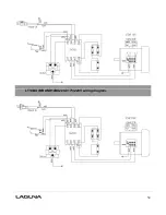
Страница 54: ...54 LT14BX MBAND14BX220 0175 220V wiring diagram...

Страница 55: ...5 5 1412 105 Upper Wheel 1 PBAND1412 175 6 1412 106 Upper Wheel Shaft 1 PBAND1412 175 7 1412 107 Upper Wheel Shaft Bracket 1 PBAND1412 175 8 1412 108 Special Nut 1 PBAND1412 175 9 1412 109 Socket Head...

Страница 56: ...175 28 1412 128 Lock Washer 10 4 PBAND1412 175 29 1412 129 Flat Washer 10 4 PBAND1412 175 30 1412 130 Tracking Window 2 PBAND1412 175 31 1412 131 Screw 10 24 1 2 4 PBAND1412 175 32 1412 132 Hex Nut 1...

Страница 57: ...213 Lock Washer 5 16 7 PBAND1412 175 2 11 1412 211 Flat Washer 5 16 6 PBAND1412 175 3 38 1412 338 Hex Nut 5 16 18 6 PBAND1412 175 59 1412 159 Carriage Bolt 5 16 18x5 8 6 PBAND1412 175 60 1412 160 Uppe...

Страница 58: ...58...

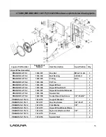
Страница 59: ...75 2 13 14BX110 175 213 Plate 1 MBAND14BX110 175 2 14 14BX110 175 214 Phillips Flat Head Screw 5 16 18x1 1 2 3 PBAND1412 175 2 15 1412 215 Lower Spindle 1 PBAND1412 175 2 16 1412 216 Hex Cap Screw M5x...

Страница 60: ...250 2 40 14BX220 250 240 Power Cord 220V 1 PBAND1412 175 2 41 1412 241 Hex Cap Screw 3 8 16x1 3 PBAND1412 175 2 42 1412 242 Flat Washer 3 8 6 PBAND1412 175 2 43 1412 108 Lock Washer 3 8 2 PBAND1412 17...

Страница 61: ...3 20mm 2 MBAND14BX110 175 2 62 14BX110 175 262 Screw 1 4 20x3 8 2 MBAND14BX110 175 2 63 14BX110 175 263 Brake Assembly 1 MBAND14BX110 175 2 63P 14BX110 175 263P Brake Pad not shown 2 pieces 1 MBAND14B...

Страница 62: ...62...

Страница 63: ...BAND1412 175 3 14 1412 314 Scale Plate 1 PBAND1412 175 3 15 1412 315 Hex Cap Screw M5x0 8x10 2 PBAND1412 175 3 16 1412 129 Flat Washer M5 2 PBAND1412 175 3 17 1412 317 Bushing 2 PBAND1412 175 3 18 141...

Страница 64: ...crew 3 8 16 2 1 PBAND1412 175 3 36 1412 336 Hex Nut 3 8 16 1 PBAND1412 175 3 37 1412 337 Phillips Flat Head Screw M4x0 7x8 1 PBAND1412 175 3 38 1412 338 Hex Nut 5 16 18 1 PBAND1412 175 3 39 1412 211 F...

Страница 65: ...65...

Страница 66: ...ND1412 175 4 13 1412 413 C Ring S12 2 PBAND1412 175 4 14 1412 414 Worm 1 PBAND1412 175 4 15 1412 415 E Ring E8 2 PBAND1412 175 4 16 1412 416 Gear Base 1 PBAND1412 175 4 17 1412 417 Bushing 1 PBAND1412...

Страница 67: ...12 435 Lock Knob 1 PBAND1412 175 4 36 1412 436 Socket Head Button Screw 1 4 20x1 2 2 PBAND1412 175 4 37 1412 437 Base 1 PBAND1412 175 4 38 1412 438 Special Bolt 2 PBAND1412 175 4 39 1412 211 Flat Wash...

Страница 68: ...et Head Button Screw 5 16 18x1 2 2 PBAND1412 175 6 5 1412 605 Flat Washer 5 16 11 PBAND1412 175 6 6 1412 606 Nylon Inserted Lock Nut 1 4 20 2 PBAND1412 175 6 7 1412 607 Fixed Plate 1 PBAND1412 175 6 8...

Страница 69: ...ate 1 PBAND1412 175 6 21 1412 621 Support Plate 1 PBAND1412 175 6 22 1412 622 Rod 1 PBAND1412 175 6 23 1412 623 Wheel 2 PBAND1412 175 6 24 1412 624 Retaining Pin R8 2 PBAND1412 175 6 25 1412 125 4 Nyl...

Страница 70: ...ication Qty 115V Industrial Work Light Optional PBAND1412 175 7 1 1412 701 Work Light 115V 1 PBAND1412 175 7 2 1412 702 Screw M4x0 7x20 4 PBAND1412 175 7 3 1412 703 Flat Washer M4 4 PBAND1412 175 7 4...

Страница 71: ...on Qty 230V Industrial Work Light Optional PBAND14BX220 250 7 1 14BX220 250 701 Work Light 230V 1 PBAND1412 175 7 2 1412 702 Screw M4x0 7x20 4 PBAND1412 175 7 3 1412 703 Flat Washer M4 4 PBAND1412 175...

Страница 72: ...ations subject to change Machines may be shown with optional accessories 2017 Laguna Tools Inc LAGUNA and the LAGUNA Logo are the registered trademarks of Laguna Tools Inc All rights reserved 2072 Alt...

Отзывы: