background image

15 


Electrical Safety (Cont’d.)


2.) Grounded, cord-connected machines intended for use on a supply circuit having a nominal 
rating less than 150 volts:


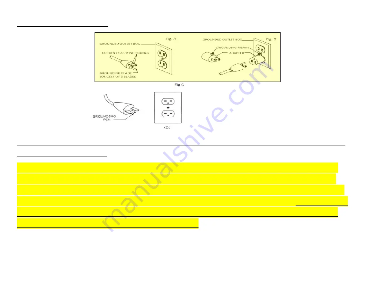
This tool is intended for use on a circuit that has an outlet that looks like the one illustrated in  
Fig. A.) The tool has a grounding plug that looks like the plug illustrated


in Fig A.)


A temporary 

adapter, which looks like the adapter illustrated in Fig B may be used to connect this plug to a 2 
Pole receptacle as shown in Fig. B.) if a properly grounded outlet is not available. 

The temporary 

adapter should be used only until a properly grounded outlet can be installed by a qualified 
electrician. This adapter is not permitted in Canada.

 The green-colored rigid ear, lug, and the like, 

extending from the adapter must be connected to a permanent ground such as a properly 
grounded outlet box.


Содержание Tools-PX-22 SHEARTEC II

Страница 1: ...1...

Страница 2: ...al Installing Universal Casters Pg 29 Power Supply Circuit Requirements pg 35 Motor Specifications Pg 36 Calibrating the Thickness Scale Pg 37 38 Calibrating the DRO Digital Read Out Pg 39 Operation P...

Страница 3: ...dly offered by Laguna Tools Every Laguna machine is engineered for years of dependable service Please feel free to contact Laguna Tools if you have a question or suggestion We appreciate working with...

Страница 4: ...e way it was received If a part or blade is being returned it must have adequate packaging to ensure no damage is received during shipping In the event the item part is determined to be damaged due to...

Страница 5: ...S A Phone 1 800 332 4094 Huntington Beach 7291 Heil Ave Huntington Beach CA 92647 U S A Phone 1 949 474 1200 South Carolina 825 Bistline Dr Suite 101 West Columbia SC 29172 U S A Phone 1 800 234 1976...

Страница 6: ...ance or modification of tools or equipment could result in serious injury and property damage There are certain applications for which tools and equipment are designed This product should NOT be modif...

Страница 7: ...7 Safety Protocols...

Страница 8: ...8 Safety Protocols Cont d...

Страница 9: ...9 Safety Protocols Cont d...

Страница 10: ...JURY MAY OCCUR 4 CUTTING DEPTH NEVER EXCEED THE MAXIMUM CUTTING DEPTH of 1 16 or 1 60 mm AS STATED IN THE SPECIFICATION FOR YOUR MACHINE IT IS FAR BETTER TO TAKE SEVERAL SMALL CUTS RATHER THAN LARGE C...

Страница 11: ...ical circuit should be used for each machine This circuit should not be less than the wiring listed below and should be protected with an appropriate circuit breaker based on the total running and sta...

Страница 12: ...f the motor uses a start capacitor a time delay fuse is required This type of fuse circuit breaker will not trip with the initial amperage needed to start the machine which is typically double that of...

Страница 13: ...ate USA or province CSA Grounding Methods Electrical Cord and Plug is not provided with Ordered Machine When a proper qualified electrical cord and plug is installed please follow the following ground...

Страница 14: ...equipment grounding conductor can result in a risk of electric shock The conductor with insulation having an outer surface that is green with or without yellow stripes is the equipment grounding cond...

Страница 15: ...ted in Fig A A temporary adapter which looks like the adapter illustrated in Fig B may be used to connect this plug to a 2 Pole receptacle as shown in Fig B if a properly grounded outlet is not availa...

Страница 16: ...tion as the plug No adapter is available or should be used with this tool If the tool must be reconnected for use on a different type of electric circuit the reconnection should be made by qualified s...

Страница 17: ...t of the machine An undersized cord will cause a drop in line voltage resulting in loss of power and overheating If in doubt use the next heavier gauge The smaller the gauge number the heavier the cor...

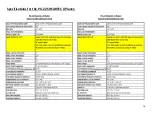
Страница 18: ...18 Specifications for the PX 22 SHEARTEC II Planer...

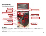
Страница 19: ...from sliding past the edge of the cutterhead Table Rollers The Roller facilitates movement of the Work Piece across the Table Limiter Min Stop Block 1 16 Emergency Stop Table Roller Table Extension Ro...

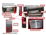
Страница 20: ...Roller Thickness Gauge Loading Hook Dust Chute Table Extension Roller Table Extension Roller Feed Speed Control Table Roller Table Rear of PX 22 Shear Tec II Planer Side of PX 22 Shear Tec II Planer...

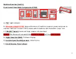
Страница 21: ...power continues to machine NOTICE To reset E STOP rotate switch clockwise until the button pops out C ON OFF Switch Starts and Stops rotation of cutterhead NOTICE The Planer will not work if the E STO...

Страница 22: ...llers Adjustable Rollers that extend for increased workpiece support Feed Speed Selector The Feed Speed Selector offers 2 two feed speeds 10 FPM 30 FPM Feet per Minute Move Lever Push Pull until it lo...

Страница 23: ...t the dust chute and calibrate the height After Setup there may be a few adjustment to be made All these adjustments are done prior to shipping the machine but if additional adjustments are required p...

Страница 24: ...BY THE OWNER AND THE DELIVERY DRIVER IF YOU FIND ANY DAMAGED ITEMS IN YOUR PACKAGE YOU MUST CONTACT LAGUNA TOOLS TO FILE A COMPLAINT IN ORDER TO RETURN DAMAGED GOODS UNDER THE LIMITED WARRANTY TO LAGU...

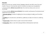
Страница 25: ...tably 2 There should be sufficient area at the back of the machine to allow access for adjustments and maintenance to be conducted 3 Adequate Lighting The better the lighting the more accurately and s...

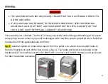
Страница 26: ...included hooks to frame of machine at each of the four corners Fig 1 The hooks and bolts are included in the hardware kit The machine can then be lifted with a harness and forklift Remove and save hoo...

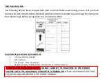
Страница 27: ...s from plastic bags before laying them out to inventory them Tools items Required Assembly Adjustment T 25 Torx Wrench included 9 16 Wrench 1 2 Wrench 5mm Hex Wrench Gauge Block Step 378IN 393IN x 75I...

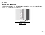
Страница 28: ...8 Assembling Machine Preparation and Setup 1 Level machine using the four leveling feet on each of the four corners Lock leveling feet into position with the nut on the leveling foot stud LEVELING FEE...

Страница 29: ...o caster mount 3 Attach swivel caster to front infeed center of frame with four bolts 1 washers 2 and nuts 3 Tighten all four bolts 4 Assemble caster wheel 2 to bracket 1 using bolt 3 and nut 4 Repeat...

Страница 30: ...type of cleaner that could damage paint Coat cleaned surfaces with WD 40 or 20W Machine Oil 3 Upper Bottom Table Roller and Table Blade Adjustment leveling Procedure 3a Bottom Table Roller Adjustment...

Страница 31: ...Roller Adjustment Procedure Cont d 1 When appropriate level is reached on the Table Height Adjustment Wheel side open or remove the Panel Cover just below the main Top Roller Axel Figure H there is Ad...

Страница 32: ...ocate 4 large Allen Set Screws on the Corners of the Planer See Figure J to adjust the amount of pressure Increase Decrease on the Top Roller use appropriate T Wrench as pictured below If the pressure...

Страница 33: ...that adjusts the pressure of the Top roller locate 4 Large Allen Set Screws on the Corners of the Planer to remove these use appropriate T Wrench as pictured below Remove Allen Set Screws completely r...

Страница 34: ...CIENT CAPACITY AND CFM FOR THIS PLANER ALWAYS TURN ON THE DUST COLLECTOR BEFORE PLANNING FIGURE H DUST CHUTE HOOD CLIPS Dust Chute Hood Clips 2 4 Screws to Mount Dust Chute Hood Clips 2 Dust Chute Opt...

Страница 35: ...motor is 7 5 HP and is typically wired for 220 Volt Single Phase 60 HZ AC current Confirm your motor electrical configuration before connecting power Before connecting the machine to the power source...

Страница 36: ...le through strain relief tighten cinch nut and attach wires to terminals 3 Re install the Connection Box Cover see Page XX for Wiring Diagram WARNING WHEN COMPLETED THE MACHINE MUST CONFORM TO THE NAT...

Страница 37: ...ece of hardwood which has been surfaced on one side with a jointer drum sander or wide belt sander With the Planer OFF Make sure the cutter head is not rotating Disconnect Power place the Calibrating...

Страница 38: ...ibrating board previously machined face Down through the planer 5 Repeat Step 5 until the planer removes the entire top surface of the calibrating board NOTICE Drawing pencil marks across the width of...

Страница 39: ...Read Out 1 Remove the battery cover of the DRO and install 2 AAA batteries DRO Digital Read Out ADJUSTMENT DRO BATTERIES DRO Button Reference and Use It is helpful to familiarize these buttons and th...

Страница 40: ...stock 3 Start Dust Collection Machine 4 Start Planer 5 Adjust Set Feed Rate Speed See Fig C Below to desired Speed 10 or 30 FPM while planer is running CAUTION PLACE THE PLANER ON A SECURE AND STABLE...

Страница 41: ...the outfeed roller Helpful Tips PLANERS WORK BEST IF ONE FACE OF STOCK IS FLAT IF NOT FLATTEN WITH A JOINTER OR DRUM SANDER IF NOT POSSIBLE TO FLATTEN ONE FACE PROCESS CUPPED MATERIAL WITH THE CUP UP...

Страница 42: ...it in optimum condition This includes inspecting all hardware for tightness ensuring the filter is clean and cleaning debris and grime from any surfaces and moving parts In addition make sure to Clea...

Страница 43: ...AND TO HOLD THE CUTTERHEAD See Figure to the Right CAUTION KNIFE INSERTS ARE DANGEROUSLY SHARP USE EXTREME CAUTION WHEN INSPECTING REMOVING OR REPLACING KNIFE INSERTS WARNING TURN PLANER OFF AND DISCO...

Страница 44: ...rew to 52 60 in lbs or 231 267 Newtons IMPORTANT When removing or rotating inserts clean sawdust from the screw the insert and the cutterhead platform Failure to this procedure or protocol will result...

Страница 45: ...45 PX 22 22 Planer Front Rear Precision Adjustment SOP...

Страница 46: ...46 PX 22 22 Planer Front Rear Precision Adjustment SOP Cont d...

Страница 47: ...47 PX 22 22 Planer Front Rear Precision Adjustment SOP Cont d...

Страница 48: ...48 PX 22 22 Planer Front Rear Precision Adjustment SOP Cont d...

Страница 49: ...49 PX 22 22 Planer Front Rear Precision Adjustment SOP Cont d...

Страница 50: ...50 PX 22 22 Planer Front Rear Precision Adjustment SOP Cont d...

Страница 51: ...51 PX 22 22 Planer Front Rear Precision Adjustment SOP Cont d...

Страница 52: ...52 PX 22 22 Planer Front Rear Precision Adjustment SOP Cont d...

Страница 53: ...53 PX 22 22 Planer Front Rear Precision Adjustment SOP Cont d...

Страница 54: ...54 PX 22 22 Planer Front Rear Precision Adjustment SOP Cont d...

Страница 55: ...55 PX 22 22 Planer Front Rear Precision Adjustment SOP Cont d...

Страница 56: ...56 PX 22 22 Planer Front Rear Precision Adjustment SOP Cont d...

Страница 57: ...57 PX 22 22 Planer Front Rear Precision Adjustment SOP Cont d...

Страница 58: ...t 1 Disconnect machine from power source 2 Open lower rear and lower left hand side panels Loosen and tighten four adjustment nuts Fig 2 to move motor plate up or down to increase or decrease belt ten...

Страница 59: ...59 Lubrication Regular monitoring and replacement of lubrication is needed 5...

Страница 60: ...lace the lubricant Oil Drain Procedure 1 Remove the Lower Gear Box Oil Drain Plug See A Pt 80 Drain dirty oil thoroughly 2 Re insert and tighten the Lower Gear Box Oil Drain Plug See A Pt 80 3 Remove...

Страница 61: ...61 Lubrication Cont d The Gear Box Oil must be changed after 2500 hours of work Instructions to remove Gear Box Oil Cover is as follows Gear Box...

Страница 62: ...n remove the following parts in order Parts 50 51 131 120 130 6 Then remove the following parts in order Parts 43 44 137 7 Remove Pt 182 Cap Screws M6 1 0x20 8 Then one can remove the Gear Box Cover P...

Страница 63: ...63 Troubleshooting...

Страница 64: ...64 Wiring WARNING REVIEW ELECTRICAL SAFETY Pg s 6 16 PRIOR TO ANY WIRING PROCEDURES...

Страница 65: ...65 Wiring Diagram 1PH...

Страница 66: ...66 Wiring Diagram 3PH...

Страница 67: ...67 Replacement Parts Diagram Cutterhead Drivetrain...

Страница 68: ...68 Replacement Parts Diagram Table Lift...

Страница 69: ...69 Replacement Parts Diagram Stand Motor...

Страница 70: ...70 Replacement Parts Table...

Страница 71: ...71 Replacement Parts Table Cont d...

Страница 72: ...72 Replacement Parts Table Cont d...

Страница 73: ...73 Replacement Parts Table Cont d...

Страница 74: ...74 Replacement Parts Table Cont d...

Страница 75: ...75 Replacement Parts Table Cont d...

Страница 76: ...76 Replacement Parts Table Cont d...

Страница 77: ...77 Replacement Parts Table Cont d...

Страница 78: ...78 Warranty...

Страница 79: ...Tec II Planer 1 27 2022 2 Added quantity of Oil 400 ml or 13 5 fl oz Removed Gage Block step Changed Table of Contents 2 08 2022 3 Page 38 Step 4 Restated Removed Carraige Lock statement Page 52 Step...

Страница 80: ...80 NOTES...

Отзывы: