background image

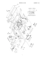
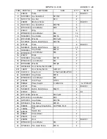
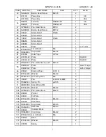
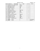
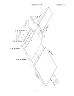
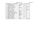
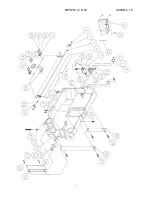
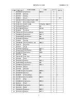
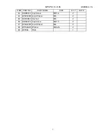
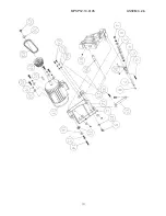
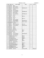
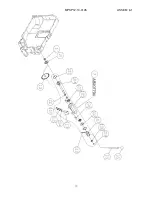
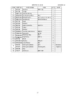
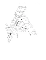
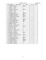
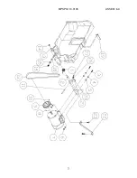
MPSP12-10-0135

ASSEM 3.1.5

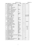
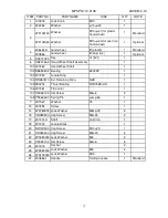
ITEM PART NO

NOTE

1

SR040600

2

207055

3

207057

4

208091

F1L

5

AB136013

101 136012
102 IC207013
103 NH040700
104 WF040805
105 200853
106 SP040700

6

SR060200

7

WS060000

8

WF061310

12 150527
15 SF089300
16 206118
17 207940
18 WF051010
19 WS050000
20 SR059200
21 207152
22 NL040700
24 207066
25 WF051010
26 WS050000
27 SR050200
28 207057A
29 207056
32 SH081000
33 NH081300
34 208093

T

35 SH060400
36 207071
37 SR080900
38 207004
39 SR080900
40 207005-1
41 SS080400
42 WF051010 Washer

M5*10

4

Shaft

1

Setscrew

M8*20

1

Shaft

1

Cap Screw

M8*45

2

Plate

2

Cap Screw

M8*45

2

Channel Base

1

Hex Head Bolt

M6*20

4

Hex Head Bolt

M8*50

1

Hex Nut

M8

1

Spring

1

Hook(R)

1

Lock Washer

M5

4

Cap Screw

M5*10

4

Hook

2

Washer

M5*10

4

Lock  Nut

M4

2

Cap Screw

M5*8

4

Plate

1

Washer

M5*10

4

Lock Washer

M5

4

Dust Port 

1

Hinge

2

Hex Head Bolt(+)/W

M8x12

4

Sponge

2

Washer

M6*

ψ

13

2

Cap Screw

M6*10

2

Lock Washer

M6

2

Fix Plate

1

Pan Head Plate

M4*35

2

Washer

M4*

ψ

8

2

M4

2

Hex Nut

1

1

Door Safety Switch

Spring

STOP CORD

0.75x2Cx2.5Mx3Y1

Door Safety Switch ASM

1

1

Cover

1

SIZE

Q`TY

PART NAME

M4*30

2

Hook(L)

1

Cap Screw

8

Содержание P12 10

Страница 1: ...P12 10 lagunatools com lagunacleanair com supermaxtools com Owner s Manual P12 10 Panelsaw MPSP12 10 0135 ...

Страница 2: ...inal purchaser must present the original receipt as proof of purchase What is Covered The warranty covers any defects in the workmanship of all parts and materials that make up the machine unless otherwise specified Any part determined by Laguna Tools to have a defect will be repaired or replaced and shipped without charge The defective item must be returned to Laguna Tools with the complaint and ...

Страница 3: ...itting rip fence P18 3 8 Fitting the saw blade P19 3 9 Riving knife P20 3 10 Changing scoring blade P21 3 11 Edge shoe hold down P23 3 12 Connection to the dust collection P24 3 13 Wiring test run P25 4 OPERATION 4 1 Saw blade lifting and tilting P26 4 2 Scoring blade adjusting P27 4 3 Control panel operation P29 4 4 Speed change P30 4 5 Setting the fence for parallel cuts P31 4 6 Sliding table P3...

Страница 4: ...EM03 Power unit ASSEM04 Saw blade angle device ASSEM05 Saw blade rise fall device ASSEM06 Scoring device ASSEM07 Outrigger arm ASSEM08 Crosscut table ASSEM09 Crosscut fence ASSEM10 Rip fence ASSEM11 Sliding table ASSEM12 Saw blade guard device ASSEM13 Angle encode ASSEM14 Accessories ...

Страница 5: ...sed The saw blade made in accordance with EN847 1 1997 shall be used on the machine Generally speaking this machine will be installed as the following conditions 1 Supply voltage 0 9 1 1 normal supply voltage 2 Source frequency 0 99 1 01 normal frequency 3 Ambient temperature 5 C 40 C 4 Altitude shall be at altitudes up to 1000m above the middle sea level 5 Relative humidity not exceed 50 at 40 C ...

Страница 6: ...ildren and visitors away All children and visitors should be kept in a safe distance from working area 6 Store idle tools cutting spindle When not in usage tools should be stored in a dry high or locked up place out of reach for children 7 Wear proper apparel No loose clothing glove neckties rings bracelets or other jewelry which may be gotten caught in moving parts Wear protective hair covering t...

Страница 7: ...16 Stand on proper position for operation Please stand in front of machine for operation 17 Use recommended ancillary equipment Consult of the instruction manual of drawing for recommended accessories The use of improper accessories may cause risk of injury to persons If ancillary equipment is removed the original guards or safety devices shall be replaced Laguna Tools and our authorized agency ar...

Страница 8: ...exceeded 29 The machine shall be not loaded with more than work piece at a time 30 During making wooden cases it will emit harmful dust User must install exhaust system for the extraction of harmful dust 31 Use correctly sharpened saw blades Observe the max Speed marked on the saw blade User shall be to select the optimum speed for saw blade 32 Report faults on the machine including guards or saw ...

Страница 9: ...achine manufacture should be used to make up the difference The use of loose rings or bushes is not permitted e Lighting it is important to provide adequate lighting around the machine 39 Guide the work piece along the rip fence and through the rotation saw blade using the push stick if necessary Any damage please replace new one that specification according below drawing 40 Do not operate this ma...

Страница 10: ... INFORMATION 6 2 1 MAIN FEATURE A Machine Body B Sliding Table C Edge Shoe D Control Panel E Overhead Guard F Crosscut Fence G Flip Stops H Crosscut Frame I Hold Down With Miter Fence Optional A B C D E F G H I ...

Страница 11: ...coring saw blade bore φ20mm Scoring blade motor power 1 HP 0 75kw Scoring blade speed 8000 rpm Cutting width 1300mm Cutting width adjustment Manual Main saw blade tilting adjustment Manual 0 45 Main saw height adjustment Manual Scoring saw adjustment Manual Saw guard Simple overhead guard as option Dust collection system For overhead guard 120 63mm 120 102mm N W G W MEAS Machine 516 618kgs 2110x12...

Страница 12: ...formation besides it shall always be kept with the machine Follow the instruction of this handbook is very important Provide adequate space for working area It also has to be cleaned and free of scrap material oil and grease This Model is a heavy duty machine The sliding table for the machine weighs is over 115kgs Use at least four strong people to lift it in position Improper lifting techniques o...

Страница 13: ...t 3 Turn the wheel see A of Fig 3 8 1 to make the whole motor unit 45 tilted Figure 3 1 3 4 Loosen motor plate knob see arrow Figure 3 1 4 5 Check if the belts are on the correct position to avoid rotational speed problem For example if it s set 4000rpm 2 sides of the belt have to be set on the 4000rpm groove Figure 3 1 5 6 Rotate the handle to right hand side to tight the belts then lock the knob...

Страница 14: ...x1 5 Assembly parts for rip fence x3 6 Assembly parts for dust collection x1 7 Assembly parts for tool box sticker flip stop x 1 8 Assembly parts for rear extension table x1 9 Assembly parts for left extension table x1 10 Assembly parts for edge shoe x1 11 Assembly parts for control panel x1 Optional parts Assembly parts for miter fence x1 Assembly parts for overhead saw blade guard D type x5 ...

Страница 15: ...ame 2 Position the fix blocks on 2 sides set points as Fig 3 3 1a 3 Lock the screws 2 sets on each side on 2 sides to fix the sliding table on the machine frame Fig 3 3 1b 4 Lock the middle fix block of sliding table on the machine frame Fig 3 3 1c 5 To assemble for the handle of sliding table fit the screws in as Fig 3 3 2 shows For packing and transport reasons some machine members are removed A...

Страница 16: ...d properly in the swing arm B Fig 3 4 1 3 Tighten lever E Fig 3 4 1 Notice To move or take off the crosscut frame withdraw lever E Fig 3 4 1 II Fitting the crosscut fence 1 Fit the T nut R Fig 3 4 1a into crosscut frame holes G Fig 3 4 1 then slide the square support pipe in see arrow of Fig 3 4 1b 2 Fit square pipe I Fig 3 4 2 to R Fig 3 4 1a of crosscut frame And tighten knob J Fig 3 4 1b 3 4 2 ...

Страница 17: ...osscut fence and sliding table exactly vertical Then lock knob M Fig 3 4 3a for fixing Notice Please tie the knob Z Fig 3 4 2a to fix the fence And adjust L Fig 3 4 3a M Fig 3 4 3a to make ext fence be exactly vertical with sliding table III Fitting the flip stop units 1 Unlocking knob N Fig 3 4 3 of the extension piece 2 Slide the flip stop unit into groove O Fig 3 4 3 Then tight P Fig 3 4 3 to f...

Страница 18: ...he extension table must be even height to cast iron table However if the extension table is lower the distance must be less than 0 2mm for smooth operation 2 If it is not aligned screw down the three screw A Fig 3 5 2 3 Then adjust the alignment with screws B Fig 3 5 2 All fitting operations in this section require approx 2 people A B Figure 3 5 2 Figure 3 5 1 Fence plate Cast iron table Extension...

Страница 19: ...the two parts for support arm 3 Lock lever E Fig 3 6 4 for support arm of overhead guard 4 Lock the round tube to the support arm as F Fig 3 6 5 5 Fit the hose supports on the support arm to fix the hose as G Fig 3 6 6 6 Screw H Fig 3 6 7 for fixing saw blade guard and fix the gas spring I Fig 3 6 8 7 Fix the hose on the blade guard and support arm by using hose clamp Fig 3 6 9 8 Fix the cable as ...

Страница 20: ...3 INSTALLATION 16 Figure 3 6 5 F Figure 3 6 6 G I Figure 3 6 8 H Figure 3 6 7 Figure 3 6 10 J Figure 3 6 9 A B C D F E G H I J K ...

Страница 21: ...e edge of the working table and extension table by fastening the fence scale ruler set with washer and lock washer 3 Slide rip fence support C Fig 3 7 1 into round bar D Fig 3 7 1 Note Move handle E Fig 3 7 1 up to release rip fence down to lock the rip fence 4 Mounting fence plate F Fig 3 7 1 to clamping assembly in upward position and tighten handle G Notice Before operation the 0 mark on the ri...

Страница 22: ...wrench to loose the screws F washer I Fig 3 8 2b remove flange G Fig 3 8 2b then remove the red plate Fig 3 8 2b Note1 Continually press the button until the screw is loosen Note2 Before fitting the saw blade make sure that the flange G Fig 3 8 2b is clean to avoid vibrations when the saw blade is rotating 7 Fit the saw blade and flange G Fig 3 8 2b then press button in hole E Fig 3 8 3a with thum...

Страница 23: ...3 INSTALLATION 19 Figure 3 10 2 F I Figure 3 8 3 Red plate Figure 3 8 2a D Figure 3 8 2b E F G E Figure 3 8 3a Figure 3 8 2 C J Figure 3 8 2c ...

Страница 24: ...thout complete tightening it 2 Position the riving knife about 3mm or 1 8 away from the nearest tooth on the main blade Gap B between saw blade and riving knife shall be 3mm approx 3 Tighten the nut A to secure the riving knife in the position Fig 3 9 1 4 Move the blade guard sliding table back to the original position B CAUTION Always install the riving knife with gloves A Figure 3 9 1 Figure 3 9...

Страница 25: ...t and one flange 8 Make sure that flanges and scoring blade are clean 9 Fit the scoring blade flange and nut then tighten nut D Fig 3 10 2 10 Remove the fixing bar from Table 11 Close the blade protect guard red cover Fig 3 10 1a 12 Release the emergency button 13 Move the sliding table back to its original position Notice for safety concern always close the blade guard when finished Fig 3 10 1 mo...

Страница 26: ...3 INSTALLATION 22 Figure 3 10 2 D C ...

Страница 27: ... trimming panel and fixes the work piece on the sliding table Notice Edge shoe is demanded in heavy duty processing Miter Fence with hold down Optional Allows precise miter cuts between 45 and 45 on the sliding table and clamps the work piece Edge shoe Optional Optional Miter fence Hold down ...

Страница 28: ...equipped with two dust ports connected to a dust collection system before operation 1 Exhaust pipe Fig 3 12 1 diameter 120mm 2 Exhaust pipe Fig 3 12 2 diameter 102mm If other machines are connected to the centralized collection system carry out a test with all collection system in operation The right operation of the collection system reduces the risks of dust inhalation Figure 3 12 1 Figure 3 12 ...

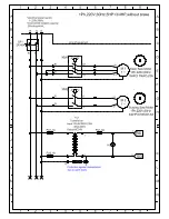
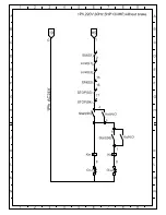
Страница 29: ...ted to the reverse phase Please change the incoming wire L2 and L3 II TEST RUN 1 Turn the main switch ON Fig 3 13 2 2 Test run the main blade rise fall 3 Test run the main blade tilting 4 Test run the main blade 5 Test run the scoring blade Make sure machine operator is to be trained for the use adjust and operation All operations requiring the demounting of machine components must be carried out ...

Страница 30: ...t the saw blade height according to the work piece thickness 3 The saw blade height must exceeds the piece thickness 1 1 5cm 4 Set the guard C Figure 4 1 1a to a max Height 4 5mm from the work piece II SAW BLADE TILTING 1 Turn hand wheel A Fig 4 1 1 to tilt the saw blade up to the demanded degree based on scale Figure 4 1 1 A B Figure 4 1 1a C ...

Страница 31: ...RING BLADE WITH THE SAW BLADE 1 The operator has to do some cutting tests 2 Loosen nut C Fig 4 2 1 3 Turn draw bar D Fig 4 2 1 to the desired position and tighten nut C Fig 4 2 1 turn clockwise the scorer move to left turn counter clockwise the scorer move to right 4 The range for traverse adjustment of the scorer is approx 2mm NOTE Test cut to check the alignment is necessary CAUTION During the m...

Страница 32: ...de thickness equal to the saw blade one B Double blade If you fit proper shims between the two elements you get the same thickness of the saw blade or a larger thickness C Conical scoring blade For aligning with saw blade of different thickness or for obtaining two chamfers on two panel edges If the edge which shall not be is only one the scoring blade may have any shape and dimension Figure 4 2 3...

Страница 33: ...ade B MAIN BLADE OFF Button Stop the main blade C SCORING BLADE ON Button Start the scoring blade Note The main saw blade must be ON for the scoring blade to start D SCORING OFF Button Stops the scoring blade E POWER LIGHT F EMERGENCY STOP Button Disconnects power to all motors in the motor cabinet A B C D E F ...

Страница 34: ...e replaced 6 Set the belts in the proper position the smallest dia gap set as 5000rpm the middle dia gap sets as the smallest dia groove set as 5000rpm the middle dia groove set as 4000rpm the largest dia groove set as 3000rpm 7 Loosen knob A Fig 4 4 1 8 Move lever B Fig 4 4 1 of belt stretcher to initial position which is totally down to stretch the belts 9 Tighten knob A Fig 4 4 1 10 Close the r...

Страница 35: ... it in order to read a value on the blade and millimeter rule of edge C Fig 4 5 1 3 Measure the distance D Fig 4 5 1 between saw blade and fence plate 4 If measured values on step 3 4 are not the same loosen ruler screws and washers then move millimeter rule until these values are matched Fig 4 5 1 Note operator can do micro adjust by using knob E after locking knob F Fig 4 5 1 then push lever B d...

Страница 36: ...just rip fence 1 Turn knob B Fig 4 5 2 to lock rip fence 2 Pull lever A up Fig 4 5 2 and turn knob D Fig 4 5 2 Then the fence unit can be micro adjusted to distance of operator s choice 3 After reaching the measure lock the fence unit by lowering lever A Fig 4 5 2 Note fence E Fig 4 5 2 can move in longitudinal direction after unlocking handles F Fig 4 5 2 After every adjustment tighten handles to...

Страница 37: ...A Fig 4 5 2 2 Loosen knob B Fig 4 5 2 3 Lift the whole rip fence unit and turn it 90 counter clockwise Fig 4 5 5a b 4 Lightly move rip fence unit out from the round bar by passing through the metal locker NOTE For the execution of special working the operators are obliged to put his hands near the tools However based on safety reasons they could use a proper pusher to move the work piece forwards ...

Страница 38: ...for placing large work piece 1 Move the frame for your desired position with handle B Fig 4 6 1 2 Lock knob A Fig 4 6 1 for fixing To remove the sliding table of the machine over the saw blade center please move the sliding table a little back for opening the second positioning design II USE OF THE HOLD DOWN 1 Loosen handle to adjust the foot height To ensure a strong panel clamping the foot shall...

Страница 39: ...E 1 Turn threaded nut C Fig 4 7 1a to make crosscut fence exactly vertical with sliding table Then lock knob D Fig 4 7 1a to fix A Fig 4 7 1 2 Turn on the machine then trimming the panel with the crosscut fence B A Figure 4 7 1 C D Figure 4 7 1a ...

Страница 40: ...ical 2 Readjust the screw C Fig 4 7 1a and make crosscut fence and sliding table exactly vertical If they are the same then the testing procedure finished II EXTEND MILLIMETER RULE For cutting panels of width exceeding 1860mm you have to use the extension part A Fig 4 7 3 and follow steps below 1 Loosen knob B Fig 4 7 3 2 Move extension part A Fig 4 7 3 Note point C Fig 4 7 3 indicates the width v...

Страница 41: ...osition of crosscut fence 2 Adjust the position for making sure the right side of the fence A Fig 4 7 4 aligning with the desired angle Note B Fig 4 7 4 part indicates the angle value 3 After adjust it to your desired angle tighten the knob F Fig 4 7 4b C D Figure 4 7 4a A B Figure 4 7 4 F Figure 4 7 4b ...

Страница 42: ... fence sideways of the sliding table rod of the fence and groove by safe solvent CHECK OF SAFETY DEVICES For safe usage of the machine the safety devices shall be efficient Check the controls for emergency stops every 2 weeks with a test With the machine under normal operating condition press the emergency button arranged on the machine the saw blade shall stop NOTE If the belts get slack the brak...

Страница 43: ...screws and nuts of limit switch whether tight or not Check all wires and electric connections near the power switch to see if there have any Check belt running normal or not If any break or failure replace it Check the load voltage and current of the motor Check the continuity of all the wires Clean the interior part of the electrical box and check the continuity of the wires Tighten the terminal ...

Страница 44: ...fe of usage as well as the best performance of the machine Weekly lubricate with grease Worms B Fig 5 2 1 and toothed sector A Fig 5 2 2 for height adjusting and tilting of the saw blade CAUTION Disconnect the electrical and pneumatic system before maintenance Figure 5 2 1 B B B B Figure 5 2 2 A ...

Страница 45: ...all motor A Fig 5 3 1 When the belt is slack it can be replaced 3 Replace the new belt then lower the motor Note Be aware of the arrow direction marked on the belt and follow it to fit the belt 4 Manually make the belt cover 2 or 3 complete turns so that it can get the right settling 5 Fit the rear cover again The belt will always be stretched by the motor weight A 5 Figure 5 3 1 ...

Страница 46: ...ver C Fig 5 3 2 of belt stretcher to initial position which is totally down at the right to stretch the belts 7 Tighten knob B Fig 5 3 2 and close the rear door Note Never replace the two belts separately Replace belts in pair instead of only one belt is necessary III BELT STRETCHING It is normal that belts get slack after long term operation and working period When it is slack the time required t...

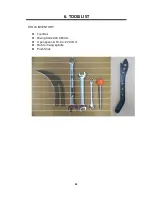
Страница 47: ...6 TOOLS LIST 43 TOOLS INVENTORY Tool Box Riving Knife 300 350mm Open spanner 19 24 27 30mm Rob for fixing spindle Push Stick ...

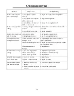
Страница 48: ...se failure 2 Change saw blade or reduce feed speed Allow motor to cool down 3 Turn off the main switch open the switch cabinet and identify which of the fuses is defective and remove it Replace new fuses only using fuses of the same rating Motor will not start or it growls on start up 1 Emergency stop button is depressed 2 Power supply fuse or circuit breaker has tripped 3 Thermal overload has tri...

Страница 49: ...or overloaded 1 Repair loose or shorted terminals or worn insulation on motor 2 Correct the low voltage conditions 3 Install correct fuses or circuit breakers 4 Reset the ampere value correctly by checking the machine information from the name plate Main blade runs backwards 1 Two of the power wires are reversed 1 Exchange wires L1 L3 in the terminal box Blade makes a squealing noise on start up 1...

Страница 50: ...ee cut Saw blade burns on the rip fence side 1 Excessive free cut on the rip fence 2 Insufficient free cut on rip fence 1 Readjust the rip fence 2 Readjust the free cut Saw blade burns on both sides 1 Incorrect free cut setting 2 Cut material jammed 3 Operating error 1 Readjust the free cut 2 Insert a riving knife in the cutting line or use a wider riving knife 3 Either moves the workpiece to the ...

Страница 51: ...2 Set the scoring blade higher Loud repetitious noise coming from machine 1 Pulley setscrews or keys are missing or loose 2 Motor fan is hitting the cover 3 Belts are defective or damaged 1 Inspect keys and setscrews Replace or tighten if necessary 2 Adjust fan cover mounting position tighten fan or shim fan cover 3 Replace belts Vibration when running or cut ting 1 Loose or damaged blade 2 Worn a...

Страница 52: ......

Страница 53: ......

Страница 54: ...MPSP12 10 0135 ASSEM 1 1 23 1 ...

Страница 55: ...049300 PART NAME SIZE Q TY Plate 1 Hex Head Bolt M10 40 2 Hex Nut M10 2 Machine frame 1 Hex Head Bolt M12 50 4 Lock Washer M12 5 Ring 4 Lock Washer M6 14 Cap Screw M6 16 14 Washer M12 ψ30 1 Button Head Screw M12 45 1 Plate 3 Button Head Screw M6 12 12 Cap Screw M5 12 4 Lock Washer M5 4 Block 2 Cap Screw M4 30 2 Lock Washer M4 2 Washer M4 ψ8 2 Stop Cord 0 75x2Cx40CMx2Y2 E 1 Door Safety Switch ASM 1...

Страница 56: ...112 200842 113 WF061310 114 200993 Button Head Screw M6 20 2 45 Power Box 1 Power Box 1 46 Terminal PB2504 4P 1 Terminal PB2504 4P 1 Pan Head Screw M5 8 2 Button Head Screw M5 12 4 Strain Relief 1 Strain Relief PG20 2 Strain Relief PG20 1 Strain Relief 1 Strain Relief 1 Plate 1 Lock Washer M6 4 Cap Screw M6 12 4 Hole Plugs HP 22 1 Plate 1 Plate 1 Pan Head Screw W M6 10 4 65 Plate 1 Plate 1 Electri...

Страница 57: ...161100 87 NH162400 88 SS080500 89 NH081300 90 136019 91 206623 for 1PH 5HP 92 205847 RAL9011 Pan Head Screw W M4x20 2 Tilt Scale acrylic 1 Washer M4 2 Hex Nut 2 Plate 1 Washer M6x19x2t 3 Plate 1 Lock Washer M6 3 Cap Screw M6 16 3 Hex Head Bolt M16x50 4 Hex Nut M16 4 Set Screw M8 25 4 Hex Nut M8 4 224 201 2 Plate 1 Plate 1 PART NAME SIZE Q TY Cord Connetor 4 ...

Страница 58: ...MPSP12 10 0135 ASSEM 1 2 4 5 ...

Страница 59: ...10 206354 11 SS162000 12 NL162400 13 205016 14 NH162400 15 207732 Dado only SIZE Q TY PART NAME Set Screw M10 20 5 Hex Nut M10 5 Left Ext Plate 1 Cap Screw M10 25 5 Table 1 Ext Plate 1 Washer M10 ψ20 5 Lock Washer M10 5 Button Head Screw M6 12 4 Table Insert aluminum 1 Set Screw M16 100 4 Lock Nut M16 4 Washer 8 Hex Nut M16 4 Table Insert aluminum 1 6 ...

Страница 60: ...MPSP12 10 0135 ASSEM 3 1 5 7 ...

Страница 61: ...80900 40 207005 1 41 SS080400 42 WF051010 Washer M5 10 4 Shaft 1 Setscrew M8 20 1 Shaft 1 Cap Screw M8 45 2 Plate 2 Cap Screw M8 45 2 Channel Base 1 Hex Head Bolt M6 20 4 Hex Head Bolt M8 50 1 Hex Nut M8 1 Spring 1 Hook R 1 Lock Washer M5 4 Cap Screw M5 10 4 Hook 2 Washer M5 10 4 Lock Nut M4 2 Cap Screw M5 8 4 Plate 1 Washer M5 10 4 Lock Washer M5 4 Dust Port 1 Hinge 2 Hex Head Bolt W M8x12 4 Spon...

Страница 62: ...ITEM PART NO NOTE 43 SR059400 44 WS050000 45 NH050800 46 SR060200 47 WS060000 48 WF061620 49 207936 Washer M6 ψ16 2 Plate 1 Cap Screw M6 10 2 Lock Washer M6 2 Lock Washer M5 2 Hex Nut M5 2 Cap Screw M5 16 2 PART NAME SIZE Q TY 9 ...

Страница 63: ...MPSP12 10 0135 ASSEM 3 2 6 10 ...

Страница 64: ...3 SF089300 36 SR080200 Cap Screw M8 10 1 Plate 1 Hex Head Bolt W M8x12 2 Washer M10 ψ40 3t 1 Washer 1 Shaft 1 Hex Head Cap Screw W M10 20 1 Washer M8 ψ18 2 Set Screw M8 12 1 Cap Screw M8 25 2 Lock Washer M8 2 23 V Belt 3VX 315 2 V Belt 3VX 300 2 22 Motor Pulley 50HZ 1 Motor Pulley 60HZ 1 Hex Head Bolt M10 40 4 Key 8 7 50 1 Washer M10 ψ40 8 Lock Washer M10 4 Washer M10 ψ40 1 17 Main Motor 1 Main Mo...

Страница 65: ...MPSP12 10 0135 ASSEM 3 3 5 12 ...

Страница 66: ...00 18 207144 F1L 19 203198 20 SS080200 7 202 Bracket Flange Button Head Screw Washer Bracket Flange Ball Bearing ψ30 Flange ψ25 4 1 1 1 Bolt M16 2p L 1 1 Washer M6 ψ19 1 M6 12 1 1 Hex Nut M12 1 75 1 Washer M16 ψ30 1 Bracket Assembly 1 SIZE Q TY PART NAME 1 1 Screw 1 Block 1 Main Shaft Assembly ψ30 1 6206LLB black 1 Main Shaft ψ30 1 Main Shaft ψ25 4 1 Ball Bearing 6206LLB black 1 Pulley 1 Counter S...

Страница 67: ...MPSP12 10 0135 ASSEM 4 10 14 ...

Страница 68: ... 3 4 Handle Lock Washer Set Screw Cap Screw Shaft Cap Screw Lock Washer Cap Screw folding handle 1 M8 2 M10 1 M6 6 6 Set Nut 2 M8 20 2 Lock Washer M8 2 M10 20 1 cast iron 1 Locate Block 1 M8 25 2 Screw 1 Lock Washer M8xψ18 2 T5 1 Washer 1 1 1 6902ZZ 1 Hand Wheel Shaft M10 ψ40 for cast iron hand wheel 1 Key 8 cast iron 1 hand wheel 8 plastic hand wheel Washer 7x7x20 Lock Knob M10 1 SIZE Q TY PART N...

Страница 69: ...MPSP12 10 0135 ASSEM 5 7 16 ...

Страница 70: ...00010 Ext Retaining Ring IS30 1 Washer Bearing Bracket Set Screw Chain 6006ZZ Washer M8xψ18 4 2 Bearing 1 Shaft 1 M6 10 2 Sprocket 1 1 Bearing Bracket ASM 1 1 7x7x20 1 Washer ψ10 ψ20 1 Washer M10 ψ27 for plastic hand wheel 1 Lock Knob M10 1 SIZE Q TY PART NAME 1 M10 ψ40 for cast iron hand wheel 1 Key 8 cast iron 1 hand wheel 8 plastic hand wheel Washer M8 4 Cap Screw M8 20 4 Lock Washer Washer M10...

Страница 71: ...00866 1 Standard M8 2 Cap Screw M8 25 4 Washer Handle Folding handle 1 PART NAME SIZE Q TY M8 4 Cap Screw M8 40 Lock Washer M8xψ18 2 Washer M8xψ18 4 Lock Washer 3 Locate Plate 1 Washer M8xψ18 3 Lock Washer M8 3 Cap Screw M8 30 2 Key 5x5x20 1 Thrust Bearing NTB1226 AS 1 Oil Filler Point 2 Nut M12 2 Cover 1 Bracket 1 Set Screw M5 5 1 Cover 1 Screw 1 Bushing Bearing DU1515 1 Thrust Bearing NTB1730 AS...

Страница 72: ...MPSP12 10 0135 ASSEM 6 1 19 ...

Страница 73: ...14 WF061310 2 115 WS060000 2 200973 1 Standard 201937 1 Optional 15 205088 1 16 100271 1 ψ30 1 ψ40 6 t 0 3 6302 Int Retaining Ring Pulley Bracket Ball Bearing M18 1 5p R42 DU2015 13 M8 25 ψ6 40 S20 M6 16 Counter Sunk Screw Washer Shaft Bushing Bearing Hex Nut M6 PART NAME SIZE Shaft Assembly Wave Washer 6004LLB Black Flange φ20 Washer Spring Pin Block Scoring Saw Blade Lock Washer M6 ψ13 Retaining...

Страница 74: ...MPSP12 10 0135 ASSEM 6 2 21 ...

Страница 75: ... 26 SR080700 27 WS080000 28 WF081818 29 SS050200 31 207039A 32 207039 Bushing 1 Bushing 1 Setscrew M5 10 2 Lock Washer M8 2 Washer M8 ψ18 2 Hex Nut 2 Cap Screw M8 35 2 adjust Knob 2 Button Head Screw M6 30 2 Setscrew M6 5 2 SIZE Q TY 1 Hex Nut 2 1 1 M8 ψ30 1 M8 1 Block ASM Cap Screw M8x20 2 1 1 M6 10 2 Screw Threads Plate Plate 2 2 Screw Threads Block 1 M5 35 4 Washer Ring Lock Washer Hex Nut Bloc...

Страница 76: ...MPSP12 10 0135 ASSEM 6 3 23 ...

Страница 77: ...07765 22 207189 F1L 23 SF089300 26 WS080000 27 SR089300 9 12 15W 1085L 50HZ 1 15W 1050L 60HZ 1 M6 20 2 ψ8X75L 1 50HZ 1 60HZ 1 Lock Washer Pulley Motor Hex Nut M8 ψ18 4 M8 2 Spring PART NAME Cap Screw Fix Pole Spring pin Washer Belt Belt Setscrew Pulley Key Lock Nut M6 2 M6 20 2 M6 ψ16 2 Lock Washer Stop Plate Washer Washer Cap Screw 1 1 M8 45 2 M8 2 1 5 5 30 1 M10 ψ40 1 M10 1 Plate 1 SIZE Q TY 1 W...

Страница 78: ...MPSP12 10 0135 ASSEM 7 6 3200mm 25 ...

Страница 79: ...0 35 207582 36 SJ059200 37 207528 GK Plate 1 M8 1 25P M10 10 Cover 13mm 10 Button Head Screw M5 8 4 Hex Nut M10 4 Hex Nut M8 10 Shaft 1 Setscrew M10 20 4 Hex Nut 1 Setscrew 3 Plate 1 Spring Washer M8 1 Cap Screw M6 20 2 Washer M20 ψ37 1 Brush 2 Washer M6 13 2 Washer M20 ψ37 1 Bearing 6004ZZ 1 Swing Arm 1 Shaft 1 Ext Retaining Ring S15 2 Bearing 6202ZZ 1 Ring 1 Ring Assembly 1 SIZE Q TY 4 1 Shaft 1...

Страница 80: ...MPSP12 10 0135 ASSEM 8 1 27 ...

Страница 81: ...33 A 201 ST040200 202 200955 203 200833 1 1 80x40 4 T Block Bearing Knob Screw Knob Screw Adjust Handle M12x1 75px57L 1 M8x50 2 T Nut PART NAME Ruler Knob Screw Support Frame Roller Bearing Support Frame ASM 55mm 6 Plug Pad 40x20 2 2 Plate M8x1 25p 2 M8x1 25px25 1 1 1 Plug 1 1 Washer Plug 6201ZZ 2 2 Washer M6x16 6 SIZE Q TY M8x30 1 38x38 2 M8x50 Lock Washer M6 6 Button Head Screw M6x16 6 Washer M8...

Страница 82: ...MPSP12 10 0135 ASSEM 9 3 29 ...

Страница 83: ...H 6 SR060500 H 7 207221 H 8 207220 H 9 SS081300 H 10 200069 H Setscrew M8 65 1 Fiber Washer 10x18 3 Fixed Block 1 Plate 1 Setscrew M6 6 2 Cap Screw M6 25 1 Knob M8x1 25px40L 1 Setscrew M8 12 2 Rotate Block 1 Fixed Block 1 Setscrew M5x5 2 Tap Screw M4x8 2 Plate 1 Nut 2 Washer M8x18 2 Locate Plate 1 Setscrew M8x25 1 Cap Screw M8x16 2 Stop Block 1 Ext Fence 1 Setscrew M6x6 1 Ext Fence 1 Sheet 1 Weari...

Страница 84: ...35 ASSEM 9 3 ITEM PART NO NOTE 11 207218 H 12 SS089300 H 13 206633 H 14 207737 H 16 WF083030 H 17 203128 H Handle 1 PART NAME SIZE Q TY Washer M8x30 1 Rotate Shaft 1 Fixed Block 1 Fixed Block 1 Setscrew M8 12 2 31 ...

Страница 85: ...MPSP12 10 0135 ASSEM 10 3 32 ...

Страница 86: ...0 9 WS080000 10 206437 End Washer 1 Cap Screw M8x16 1 Lock Washer M8 1 Screw M12x1 75px115L 4 Hex Nut M12 8 Rip Fence Housing Assembly 1 Counter Sunk Screw M6 16 2 Fixed Plate 1 Shafts 2 Lock Nut M8 2 Plate 1 Hex Head Bolt M6 16 2 Eccentric Ring 2 Seat 1 Eccentric Shaft 1 Washer ψ20 ψ36 1 Steel Ball ψ8 1 Spring 1 Set Screw M10 10 1 M8 1 Retaining Ring S20 1 Lock Washer M8 1 SIZE Q TY Ring 1 PART N...

Страница 87: ...NH121900 20 NH061000 H 21 WF061620 H 22 WS060000 H LM206306 Standard LM001042 Optional Lock Washer M6 1 23 Ruler mm 1 Ruler inch mm 1 Hex Nut M6 1 Washer M6x16x2 1 Lock Washer M12 4 Hex Nut M12 4 Measuring Rule Rail 1 Washer M13x22x2 5 8 Button Head Screw M6 12 3 Washer M6 16 3 Setscrew M6x10 1 Ring Stop 1 Round Rail 1 PART NAME SIZE Q TY 34 ...

Страница 88: ... Optional 2375320M Optional 2 2375320M 1 T3 3 SJ060200 4 203520 5 SR080500 6 206581 7 SR080500 1 SIZE Q TY M8 25 8 1 375x2500mm 1 375x3200mm 1 M8 25 4 1 Fixed Block Table PART NAME Table M6 10 3 2 Hander Cap Screw Cap Screw Fixed Block Hex Head Bolt 35 ...

Страница 89: ...MPSP12 10 0135 ASSEM 12 6 4 36 ...

Страница 90: ... 112 NH101700 Washer M10 ψ25 2 Hex Nut M10 2 Handle MS 737 1 A 330 1 Case 1 Pilot Lamp YK 24V φ22 W 1 Cap Screw M10 45 2 Panel 1 Switch Button OFF R2 PNF 1B R 2 Emergency Stop Button R2 PNR4 1B R 1 M5 10 6 Switch Button ON R2 PNF 1A G 2 Fixed Bracket 1 Case ASM 1 M8x18 4 Cap Screw M8x25 4 Hex Nut M20 3 M8 4 Washer Washer ψ22 ψ60 t8 3 Screw M20 130 3 Hex Nut M12 1 Hex Head Bolt M12X70 1 Pad 8 Cap S...

Страница 91: ... 207875 78 WF051210 79 WS050000 80 SR050200 83 NH061000 Hex Head Bolt M10X30 1 Hex Nut M16 1 Thrust Bearing LFW 2015 2 Holder N TH 34B 7 Cap Screw M6 10 7 Washer M6 ψ16 3 Fixed Plate 1 Cap Screw M6 20 2 Lock Washer M6 2 Strain Relief N MGQ32 34B 2 Pad 2x300x7 5 M M 5 Cap Screw M5 10 6 Plastic Corrugated Tubing 1 Plate 1 Lock Washer M5 6 Stop Cord 1 Control Panel Cord 1 Fixed Plate 1 M5 ψ12 2 Lock ...

Страница 92: ...MPSP12 10 0135 ASSEM 12 10 39 ...

Страница 93: ...1 R Elbow Type Clamp 1 Washer M8x18 2 Plate φ350 400 1 Washer M6 ψ19 3 Hex Head Bolt M10 35 2 Plate φ300 350 1 Cap Screw M6 45 1 Lock Washer M10 2 Dust Port 1 Button Head Screw M6 30 5 Lock Washer M6 2 Washer M6 ψ19 2 Dust Port 1 Cap Screw M6 12 2 Lock Washer M6 2 Cap Screw M6 12 2 Cap Screw M6 25 1 Lock Washer M6 2 Hex Nut M6 1 SIZE Q TY Lock Nut M6 2 Hex Head Bolt M10 35 2 Fixed Plate 1 Copper W...

Страница 94: ...7868 305 SP040200 306 SI060200 307 207883 PART NAME SIZE Q TY Plate 2 Cap Screw M6x10 6 Shaft 1 Lock Washer M6 6 Copper Washer ψ24 ψ16 0 3t 2 Rear Cover ASM 1 Tap Screw M3 5x25 7 Rear Cover 1 Front Cover 1 Tap Screw M4x10 3 Knob 1 Washer M8x18 1 Hex Nut M8 1 Warning Label 1 Warning Label 1 Warning Label 1 Protection Hood ASM 1 Guard 1 Pan Head Screw M4 10 6 Protection Hood 1 Roller ASM 2 Pan Head ...

Страница 95: ... 207069 107 207145 108 207065 109 207068 110 NH602300 111 200807 112 205253 113 200809 114 205830 SIZE Q TY 1 1 1 M8 P1 25 1 AB207065 1 T Nut 1 1 Washer Large Washer 1 1 1 Shaft Hex Nut Shaft Pin Down Press ASM PART NAME Ball Knob Adjust Handle 1 S14 1 Handle Bar Down Press Spring Ext Retaining Ring Cam 1 5 16 1 1 42 ...

Страница 96: ...MPSP12 10 0135 ASSEM 14 2 ITEM PART NO NOTE 1 200939 2 WF123030 3 992496 t 2 4 201849 T Nut Handle PART NAME Plastic Washer Washer SIZE Q TY 1 1 M12x30 1 φ13xφ25 1 M12x1 75p 43 ...

Страница 97: ...14 3 ITEM PART NO NOTE 1 AB201830 101 201830 102 PS051600 103 WF102025 104 203718 105 201829 T Nut M10x1 5p 1 SIZE Q TY Knob M10 1 1 1 1 φ5xφ16 1 M10x25 Washer Edge Shoe Plate Assembly PART NAME Spint Pin Edge Shoe Plate 44 ...

Страница 98: ...MPSP12 10 0135 ASSEM 14 4 5 45 ...

Страница 99: ...Adjust Handle Fixed Base for D E M sliding table Fixed Base for B1 sliding table Stop Bar 2 T Bolt 2 1 Fixed Base for 1600mm sliding table 1 1 SIZE Q TY 1 1 for E sliding table 1 for 1600mm sliding table Fixed Block Pan Head Bolt 1 M5 3 Pointer Cap Screw Hex Nut Miter Gauge Body 1 M4 9 2 1 M8 ψ30 1 Spring plungers with ball 1 End Washer Shaft T 3MM 1 M4 16 2 Pan Head Bolt 1 Fasten Handle PART NAME...

Страница 100: ... 1 949 474 1200 or email customerservice lagunatools com Laguna Tools is not responsible for errors or omissions Specifications subject to change Machines may be shown with optional accessories 2018 Laguna Tools Inc LAGUNA and the LAGUNA Logo are the registered trademarks of Laguna Tools Inc All rights reserved ...

Отзывы: