10
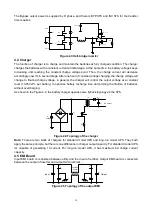
The Bypass output power is supplied by R phase, and there is BYP.STS and INV.STS for the transfer
time requires.
C
Z
D
2
U
I
U
O
L
D
1
N
C
1
C
2
Q
1
Q
2
U
BUS+
U
BUS-
N
R Phase
BYP.STS
INV.STS
INV.RLY
Figure 4.3 Half-bridge inverter
4.4 Charger
The function of charger is to charge and maintain the batteries at fully charged condition. The charger
charges the batteries with a constant current at initial stage. At the same time, the battery voltage keeps
increasing until reaching the constant charge voltage point. Then, the charge current will decrease
accordingly, now it
’s in second stage. After one hour of constant voltage charging, the charge voltage will
change to floating charge voltage, in general, the charger will control the output voltage at a constant
level (13.65V±1% per battery) to optimize battery recharge time and prolong the lifetime of batteries
without overcharging.
As shown in the Figure 4.4, the battery charger applies same flyback topology as the SPS.
…………
C
p
C
1
R
S
D
1
Q
1
DC Output
TX
R
Phase
REC
+
-
Figure 4.4 Topology of the charger
Note:
There are two kinds of chargers for standard model UPS and long-run model UPS. They both
apply the same principle, but there is one difference in charger output capacity. For standard model UPS,
it
’s capable of generating 1A current. For long-run model UPS, it has maximum 4A charge current
capacity.
4.5 EMI Board
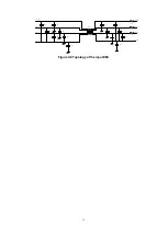
Input EMI board is connected between utility and the input of rectifier. Output EMI board is connected
between the output of inverter and output terminal block.
C
X
C
Y
C
Y
C
Y
C
Y
C
X
Input
Output
Common
Choke
Figure 4.5 Topology of the output EMI
Содержание G31 10K
Страница 37: ...37 ...


