125
Expert(t) 2000
TM
Maintenance Manual
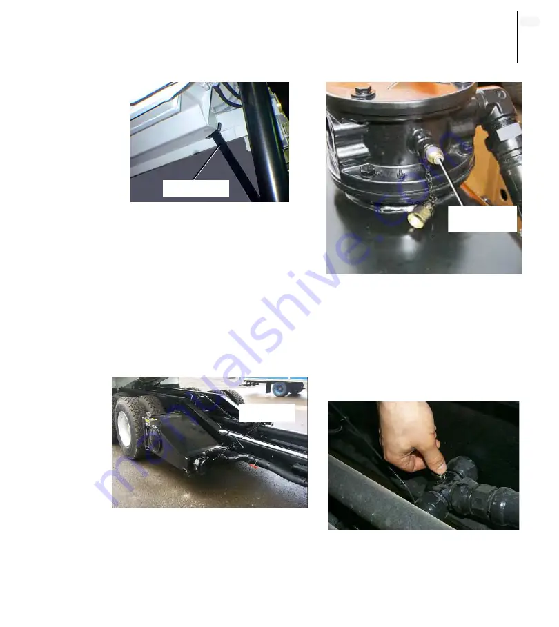
Figure 181. Body safety prop
5.
Disengage the pump and stop
the engine;
6.
Locate the oil sampler coupler
on the side of the hydraulic tank
(Figure 182. “Standard hydraulic
tank”), or on the top of it in the
case of a saddle type tank
(Figure 183. “Saddle-type
hydraulic tank”).
Figure 182. Standard hydraulic tank
Figure 183. Saddle-type hydraulic
tank
7.
Remove the cap from the
coupler and clean the sampler
coupler using a clean rag
(“Sampler coupler” on
page 125);
Figure 184. Sampler coupler
Safety prop
Coupler
Coupler
Содержание expert 2000
Страница 1: ......
Страница 2: ......
Страница 3: ...MAINTENANCE MANUAL 12 14 2006 Part 55379 ...
Страница 4: ......
Страница 10: ...viii Table of Contents ...
Страница 96: ...86 CHAPTER 3 Maintenance Figure 141 Proximity switch front view ...
Страница 99: ...89 Expert t 2000TM Maintenance Manual Figure 142 Main hydraulic valve Tailgate Packer Body Hoist Crusher Panel ...
Страница 118: ...108 CHAPTER 3 Maintenance Figure 170 Ball valve in closed position ...
Страница 140: ...130 CHAPTER 4 Lubrication PACKER ...
Страница 141: ...131 Expert t 2000TM Maintenance Manual BODY CHASSIS HINGES ...
Страница 142: ...132 CHAPTER 4 Lubrication HOPPER SECTION STANDARD VERSION ...
Страница 143: ...133 Expert t 2000TM Maintenance Manual CRUSHER PANEL ...
Страница 144: ...134 CHAPTER 4 Lubrication FULL WIDTH TAILGATE ...
Страница 154: ...144 CHAPTER 5 Troubleshooting ...
Страница 156: ...146 Appendix CONNECTORS Commonly used Electrical Connectors Deutsch AMP ...
Страница 160: ...150 Appendix Lights Symbol Description Part number 6 12V STROBE LIGHT ELL02765 12V AMBER FLASHING LIGHT ELL02855 ...
Страница 168: ...158 Appendix ...
Страница 170: ...160 Appendix ...
Страница 171: ......
Страница 172: ......


