Hydraulic System
133
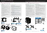
Figure 5-10 Suction block
9.
Attach the pump to a suitable lifting device and remove all 5/8” bolts that hold the pump to the
PTO extension shaft.
10.
Remove the pump.
11.
Install the new pump using a suitable lifting device.
Before attempting to install the new pump, it is very important to check the porting configuration
of that pump; the ports on the replacement pump must be positioned the same way as on the
uninstalled pump. If not, proceed with changing the porting configuration of the new pump.
The replacement pump must be oriented in such a way to facilitate easy reconnection to the
hydraulic system and attachment to the chassis frame.
Go to
to know how to change the porting configuration of the new pump; procedure
N
OTE
:
If the old pump had an o-ring on the front cap, the replacement pump must have a new o-ring
installed. Make sure this is done before installing the pump.
Содержание automizer
Страница 1: ...AUTOMIZERTM MAINTENANCE MANUAL...
Страница 2: ......
Страница 3: ...AUTOMIZER MAINTENANCE MANUAL...
Страница 10: ...viii Table of Contents...
Страница 16: ...6 Introduction...
Страница 30: ...20 Safety 7 Put the safety pin back in place...
Страница 83: ...General Maintenance 73 Figure 3 72 Rubber seal...
Страница 114: ...104 Lubrication Figure 4 10 Lube charts on vehicle right hand side...
Страница 115: ...Lubrication 105 Figure 4 11 AUTOMIZER lubrication charts...
Страница 116: ...106 Lubrication...
Страница 122: ...112 Lubrication Hopper Door Lubrication Points Hopperdoor latch Hopper door hinges Hopperdoor latch...
Страница 123: ...Lubrication 113 Packer Lubrication Points 1 Remote grease fittings for rear cylinder pins Rollergrease fitting...
Страница 124: ...114 Lubrication Packer Lubrication Points 2 Grease fitting LH side front cylinder pin...
Страница 125: ...Lubrication 115 Chute Lubrication Points Co Mingle Vehicles Pump Drive Shaft U Joint Grease fittings...
Страница 126: ...116 Lubrication Sump Box Hinges Grease fittings...
Страница 160: ...150 Hydraulic System Figure 5 29 External relief valve adjustment screw External relief valve adjustment screw...
Страница 180: ...170 Pneumatic System...
Страница 183: ...Troubleshooting 173 Figure 8 4 Ball end hex wrench metric and SAE...
Страница 192: ...182 Troubleshooting Figure 8 9 Tailgate locking mechanism...
Страница 220: ...210 Lifting Arms Figure 10 1 Mounting bolts Figure 10 2 Rollers and bearings Figure 10 3 Bolt locks Bearings Rollers...
Страница 221: ...Lifting Arms 211 Figure 10 4 Right Hand gripper Figure 10 5 Hoses and connections 5 Check for loose nuts and bolts...
Страница 239: ...Lifting Arms 229 Figure 10 23 Arm w 96 gallon gripper...