background image

Chapter 6: Maintaining The Station 


Product Service 1-800-522-7658 

15 

Service Operations 


Always disconnect the power cord from wall outlet before beginning service 
operations. 
 
Do not damage internal wiring or other components while service panels are 
removed.  If internal wiring or components are damaged, do not restore power, 
contact Labco

nco’s Product Service Department immediately. 

 
Wear all required Personnel Protective Equipment (PPE) during service 
operations.  At a minimum, this includes: eye protection, breathing protection, 
skin protection.  Do not wear loose fitting clothes that can catch on internal 
surfaces. 


Prefilter Replacement: 

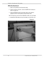
1.  Remove the filter cover by pulling the two latches down at the same 

time. Swing the top of the panel away from the filter module, and then 
lift the panel away from the unit, as shown in Figure 6-1.  

2.  Pull the prefilter straight away from the HEPA filter, releasing it from 

the three prefilter clamps.  

3.  Install the new prefilter, noting the orientation (the airflow arrow should 

point toward the HEPA filter). Reinstall the filter cover.  


Figure 6-1 

Содержание Protector 3410000

Страница 1: ...Protector Downdraft Powder Stations Models 3410000 3410001 3410020 3410021 3410022 3410023 3410024 3410025 ...

Страница 2: ...7 30 a m and 5 30 p m Central Standard Time Part 3412800 Rev E ECO L627 Warranty Labconco Corporation provides a warranty to the original buyer for the repair or replacement of parts and reasonable labor as a result of normal and proper use of the equipment with compatible chemicals Broken glassware and maintenance items such as filters gaskets light bulbs finishes and lubrication are not warrante...

Страница 3: ...t Requirements 3 Electrical Requirements 3 CHAPTER 3 GETTING STARTED 4 Unpacking the Station 4 6 CHAPTER 4 PERFORMANCE FEATURES AND SAFETY PRECAUTIONS 7 Directional Airflow 8 Prefilter 8 HEPA Filter 8 9 Blower 9 Station Air Intake and Exhaust 9 Safety Precautions 10 11 CHAPTER 5 USING THE STATION 12 Fan Switch 12 Filter System Light 12 Dusting in the Station 13 ...

Страница 4: ...ce Schedule 14 Service Operations 15 17 Prefilter Replacement 15 HEPA Filter Replacement 16 Resetting a Circuit Breaker 17 CHAPTER 7 TROUBLESHOOTING 18 APPENDIX A COMPONENTS 19 APPENDIX B DIMENSIONS 20 APPENDIX C SPECIFICATIONS 21 APPENDIX D ACCESSORIES 22 ...

Страница 5: ...any of its features to us The Downdraft Powder Station offers many unique features to enhance performance and flexibility To take full advantage of them please acquaint yourself with this manual and keep it handy for future reference If you are unfamiliar with how downdraft stations operate please review Chapter 4 Performance Features and Safety Precautions before you begin using the station Even ...

Страница 6: ...ead this chapter to learn Space requirements Location requirements Electrical power requirements Exhaust requirements Refer to Appendix C Specifications for complete station electrical and environmental conditions specifications and requirements Space Requirements The dimensions for the downdraft station are shown in Appendix B Dimensions Clearance A minimum clearance of at least 6 inches 150 mm i...

Страница 7: ...tation should have no obstructions within 6 inches of the exhaust discharge Electrical Requirements The Downdraft Station models have the following electrical requirements Model Requirements 3410000 01 115 VAC 60 Hz 1 Amp 3410020 25 230 VAC 50 60 Hz 0 5 Amp Note An outlet with a circuit breaker rated at 10 amps for 115 volt models 5 amps for 230 volt models should be located as close as possible t...

Страница 8: ...ully remove the outer carton and inspect the station for damage that may have occurred in transit If the station is damaged notify the delivery carrier immediately and retain the entire shipment intact for inspection by the carrier Note United States Interstate Commerce Commission rules require that claims be filed with the delivery carrier within fifteen 15 days of delivery Do not return goods wi...

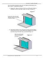
Страница 9: ...located in the bottom corners of the filter module as shown in Figure 3 1 Engage the work surface pan With the lower pins on the side of the filter module 2 Set the work surface on top of the pan by hooking the rear flange under Ensure the work surface flange goes behind the front panel the bottom edge of the filter cover as shown in Figure 3 2 Figure 3 1 Figure 3 2 Ensure the work surface flange ...

Страница 10: ... gap between the front panel and the filter module Ensure the side panel pin engages the oversized holes on the edges of the work surface 4 Plug the power cord into the filter module The plug socket is located on the top right rear corner of the station The unit is ready for use Figure 3 3 Ensure the pins go into the oversized holes ...

Страница 11: ... io on ns s The Protector Downdraft Powder Station operates using the following principles Directional airflow Prefiltration of large particulates by an inlet prefilter Filtration and retention of particulates by a High Efficiency Particulate Air HEPA filter The major components in the system are The prefilter The HEPA filter The blower to force air through the station ...

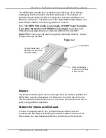
Страница 12: ...trated in Figure 4 1 Prefilter The prefilter is a disposable pleated paper filter The filter has a Minimum Efficiency Reporting Value MERV of 8 meaning it removes 70 85 of particles 3 0 10 microns in size See Appendix A for reorder part numbers HEPA Filter HEPA filters are disposable dry type particulate filters The filter material or media is typically made of borosilicate microfibers formed into...

Страница 13: ...rvice Department at 1 800 522 7658 or 816 333 8811 Note HEPA Filters are only effective against particulate material Gases will pass through the filter Blower The blower assembly pulls room air through the work surface prefilter and HEPA filter and then discharges the filtered air out of the top of the unit The Downdraft Powder Station uses a motorized backward curved fan for quiet energy efficien...

Страница 14: ...erating volatile toxic chemicals are prohibited The media of the filter is fragile and should not be touched Avoid puncturing the HEPA filter during installation or normal operation If you suspect that a HEPA filter has been damaged DO NOT use the station contact Labconco at 800 821 5525 or 816 333 8811 for further information The HEPA filter in the station will gradually accumulate airborne parti...

Страница 15: ... during service operations At a minimum this includes eye protection breathing protection skin protection Do not wear loose fitting clothes that can catch on internal surfaces After service verify safe state of use before using the product Contact Labconco s Product Service Department for questions on determining safe state of this product ...

Страница 16: ...wer drawing air into and through the station Fan Switch Filter System Light Filter System Light The filter system light will illuminate if the airflow across the filters is insufficient If lit first inspect or replace the prefilter If lit with a clean prefilter replace the HEPA filter NOTE If the Filter System Light illuminates during use finish the dusting of the evidence in the station and then ...

Страница 17: ...ence during dusting so that air flows around all surfaces of it and directly into the perforated work surface Do not overload the station Do not place objects directly on top of the perforated work surface in a manner that would obstruct the downflow Do not obstruct the perforated work surface or the exhaust air discharge on top of the station Shutdown Turn off the station Wipe down the perforated...

Страница 18: ...ethanol or a suitable cleaner clean the perforated work surface and work surface pan Operate the system blower noting if the filter system light turns on Monthly or more often as required Using a damp cloth or LabSolutions Glass Surface Wipes Labconco part 1570000 clean the exterior surfaces of the station particularly the perforated work surface to remove any accumulated dust All weekly activitie...

Страница 19: ...uring service operations At a minimum this includes eye protection breathing protection skin protection Do not wear loose fitting clothes that can catch on internal surfaces Prefilter Replacement 1 Remove the filter cover by pulling the two latches down at the same time Swing the top of the panel away from the filter module and then lift the panel away from the unit as shown in Figure 6 1 2 Pull t...

Страница 20: ... nut driver or wrench remove the HEPA filter clamps as shown in Figure 6 2 3 Pull the HEPA filter away from the filter frame and install the replacement filter with its gasket facing the filter frame NOTE Take care not to touch the HEPA filter media It is very fragile 4 Reinstall the HEPA filter clamps the prefilter and the filter cover Figure 6 2 ...

Страница 21: ...intaining The Station Product Service 1 800 522 7658 17 Resetting a Circuit Breaker To reset the circuit breaker located on the top rear of station depress the white button until it sets Figure 6 3 Circuit Breaker ...

Страница 22: ...e PROBLEM CAUSE CORRECTIVE ACTION Station blower won t turn on Unit not plugged into outlet Plug the station into appropriate electrical service Check connection to the top of station Circuit breaker tripped Reset circuit breaker Filter System Light turns on Blockage of the prefilter Check the prefilter replace if needed Ensure that there is no obstruction of the exhaust on top of the station HEPA...

Страница 23: ...ntity Part No Description 1 1 3768903 Prefilter 2 1 6938100 HEPA Filter 3 1 3897300 Pressure Switch 4 1 1307000 Rocker Switch 5a 1 1331300 Power Cord 115 VAC N America 5b 1 1332600 Power Cord 230 VAC UK 5c 1 1336100 Power Cord 230 VAC EN Schuko 5d 1 1332700 Power Cord 115 VAC China Australia 6 1 3932600 Blower 115 VAC 6a 1 3932601 Blower 230 VAC ...

Страница 24: ... 7658 20 A Ap pp pe en nd di ix x B B D Di im me en ns si io on ns s B 1 Accessory Shelf 4 4 112mm 16 0 406mm 25 8 655mm TOP FRONT A Dimension A 2 foot wide units 24 0 3 foot wide units 36 0 SIDE 15 1 384mm 1 9 48mm 18 8 478mm ...

Страница 25: ...ratures up to 88 F 31 C decreasing linearly to 50 relative humidity at 104 F 40 C Main supply voltage fluctuations not to exceed 10 of the nominal voltage Transient overvoltages according to Installation Categories II Overvoltage Categories per IEC 1010 Temporary voltage spikes on the AC input line that may be as high as 1500V for 115V models and 2500V for 230V models are allowed Used in an enviro...

Страница 26: ...Product Service 1 800 522 7658 22 A Ap pp pe en nd di ix x D D A Ac cc ce es ss so or ri ie es s Transition Kit 3413300 Allows two separate stations to be tied together 1 lb 0 5kg ...

Отзывы: