background image

10 

2.5 

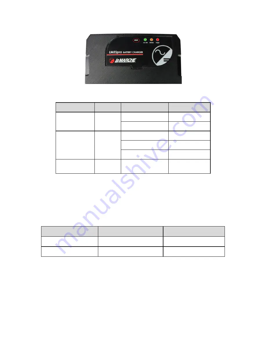
Indication Details 

Figure 11 

 LMESpro Front View 

LED/Description 

LED Color 

LED Status 

Indication 

AC ON 


AC Status 

Green 

ON 

AC ON 

OFF 

AC Out of Range 

STATUS 


Charging Status 

Orange 

Blink with 5 sec. delay 

Bulk Charging 

Blink with 20 sec. delay 

Absorption Charging 

Solid Glow 

Float Charging 

FAULT 


Charger Status 

Red 

ON 

Charger Failure 

Table 3 

 LED Indicators 

2.6 

Fault Indications and Alarms 

OUTPUT  HIGH  DC: 

If  a  24VDC  battery/HCAP  is  connected  to  the  LMESpro  charger  when  12VDC  mode  is 

selected, the charger will shut down in high DC protection. No damage will occur to the charger. The charger will 

restore its output once it reaches the recovery voltage. Refer to the table below for the high DC voltage shutdown 
and recovery voltages.


Charger Mode Selected  High DC Shutdown Voltage  High DC Recovery Voltage


12V 

15.3V 

14V 

24V 

30.6V 

28V 

Table 4 

 High DC Output Alarm Thresholds 

OUTPUT LOW DC:  

When the battery/HCAP drops below 6V for a 12V system or below 12V for a 24V system, it 

will cause the charger to turn OFF. The charger will turn on after 2 minutes in soft start mode to slowly charge 
the battery/HCAP.


OUTPUT SHORT CIRCUIT: 

When an output short circuit occurs, or output exceeds 15A, the FAULT LED will 

indicate.  Remove short circuit and reset the AC power to resume normal operation. 


Содержание LMES Pro

Страница 1: ...w lamarchemfg com 106 Bradrock Dr Des Plaines IL 60018 1967 CPN 144074 Instruction Drawing Number P25 LLMESP 01 Tel 847 299 1188 Fax 847 299 3061 Revision A00 Rev Date 03 21 ECN 22774 La Marche Manufacturing Company www lamarchemfg com LMESpro Smart Battery HCAP Charger Installation and Operation Manual ...

Страница 2: ...tact with any internal components Do not operate this unit outside the input and output ratings listed on the unit nameplate Do not use this unit for any purpose not described in the operation manual Mechanical Safety This unit or parts of the unit may get very hot during normal operation use care when working nearby Do not expose equipment to rain or snow Always install in a clean dry location Do...

Страница 3: ...y that you have all the necessary parts as per your order for proper assembly CAUTION Failure to properly file a claim for shipping damages or provide a copy of the claim to La Marche may void warranty service for any physical damages reported for repair Returns for Service Save the original shipping container If the product needs to be returned for service it should be packaged in its original sh...

Страница 4: ...l Connections 4 1 2 1 AC Input Connections 5 1 2 2 DC Output Connections 6 1 2 3 Remote Temperature Probe Connection 6 2 Operation 7 2 1 Initial Setup 7 2 2 DIP Switch Settings 7 2 3 Lead Acid Four Stage Charge Curve 8 2 4 HCAP Four Stage Charge Curve 9 2 5 Indication Details 10 2 6 Fault Indications and Alarms 10 2 7 Reset Button 11 3 Service 12 3 1 User Serviceable Parts 12 3 2 Performing Routin...

Страница 5: ...l AC Input and the output is selectable for either 12 VDC or 24 VDC Understanding the Model Number The LMESpro model number is coded to describe the options that are included Find the model number on the nomenclature nameplate of the charger Follow the chart to determine the configuration of your battery charger Optional Accessories Included in the Charger This charger may have been outfitted with...

Страница 6: ... the temperature to prolong the life of the battery or HCAP The charger also detects an open or shorted external probe When the temperature probe is not connected or defective temperature compensation is disabled High DC Protection If 24V DC battery is connected to the charger when 12V mode is selected it will shut down in High DC protection No damage will occur to the charger Output Short Circuit...

Страница 7: ...n an upright position as shown in Figure 1 to promote convection air flow Provide clearance for at least 6in 152mm of free air must be maintained on the left right sides and at least 6 152mm top bottom sides for cooling Maintain 36in 914mm or more of clearance at the front of the charger in order to allow for operation and maintenance Install the LMESpro using appropriate hardware on the wall When...

Страница 8: ...at 90 C or 194 F NOTE These are minimum recommended sizes per La Marche Standards The National Electrical Code NEC and Local Wiring Codes must be followed The LMESpro utilizes spring loaded push in style connectors It is recommended to use wire crimp ferrules on the AC DC field wiring when installing the charger however it is not absolutely necessary Crimp ferrules will prevent wire strands from f...

Страница 9: ...s For AC Terminal location refer to Figure 5 For AC systems with a line and neutral such as 120Vac service in North America connect Line to the L neutral to the N For AC systems with 2 hot leads or Line 1 Line 2 such as 240Vac service in North America connect Line 1 to L Line 2 to N All installations require the Ground terminal to be connected to the AC service Ground Earth wire All installations ...

Страница 10: ...terminal is connected to the negative battery terminal CAUTION Do not touch the charger while it is in operation or just after de energizing the charger as the LMESpro heat sink can become very hot during operation 1 2 3 Remote Temperature Probe Connection It is recommended to use temperature compensated charging with Lead Acid HCAPS especially in environments having a wide temperature range La Ma...

Страница 11: ...of the wires pull out of the connector Read section 2 for Initial Setup to set the DIP switches to match the Battery HCAP Read and understand all safety precautions in the manual Apply AC power to the input terminals of the LMESpro to start up the charger after setting the DIP switches for the desired application per 2 2 2 2 DIP Switch Settings The LMESpro output can be configured to account for v...

Страница 12: ...e than 90 seconds Provides full current until the battery reaches 102 of its absorption voltage reference Absorption When the battery has recharged to the Absorption voltage level constant voltage regulation is used to prevent heating and excessive battery gassing The charger will hold the absorption voltage mode until the battery is determined to be fully charged The absorption mode detects the f...

Страница 13: ...ates to the Bulk Charge mode Note in most applications the HCAP wouldn t regularly be discharged to a voltage that would invoke operating in the Pre Conditioning mode Bulk Charge In this stage the HCAP voltage has not yet reached the Absorption voltage and 100 of rated current is used to recharge the HCAP The LMESpro provides full rated constant current until the HCAP reaches the Absorption voltag...

Страница 14: ...ion No damage will occur to the charger The charger will restore its output once it reaches the recovery voltage Refer to the table below for the high DC voltage shutdown and recovery voltages Charger Mode Selected High DC Shutdown Voltage High DC Recovery Voltage 12V 15 3V 14V 24V 30 6V 28V Table 4 High DC Output Alarm Thresholds OUTPUT LOW DC When the battery HCAP drops below 6V for a 12V system...

Страница 15: ...pt Invoke a reset by pressing the Reset Button for 0 5 seconds Example If an output short circuit is detected the charger will protect itself see section 2 6 Output Short Circuit Every few minutes the charger will automatically attempt to restart If the short is still present the charger will continue to attempt restart every few minutes and only fully restore output when the short circuit is remo...

Страница 16: ...that the AC power is off Disconnect the battery HCAP from the charger Verify that no voltage is present by using a voltmeter at all input and output terminals 3 1 User Serviceable Parts Other than the AC DC fuses there are no user serviceable parts within the LMESpro Only replace fuses with the same current and voltage ratings never substitute a larger ampacity See Figure 13 Figure 13 Location of ...

Страница 17: ...k unit specifications against customer order 3 Check AC input connection and verify the AC supply measures within the specified range 4 Measure AC voltage if power outage occurred 5 Check for shipping damage loose connections broken wires etc 6 Certain failures can be caused by defective batteries make sure batteries are free from defects 7 If the red Fault LED is illuminated try using the Reset b...

Страница 18: ...ge Status Flashing Green for Bulk Solid Green for Float User Programmable Settings 1 12 24 Volt Output 2 Battery type or HCAP Ambient Operating Temp 40 C to 50 C Derate 70 C internal shutdown 85 C internal Storage Temp Range 40 C to 70 C Protections Output Overcurrent Output Short Circuit Output Reverse Polarity AC Fuse Internal DC Fuse Internal Thermal Protection Transient overvoltage protection ...

Страница 19: ...minum Calculating Wire Size Requirements AVD K LF A CMA Calculating Current Carrying Capacity of Wire Table 5 Wire Size Area Table K LF AVD CMA MaxAmp Example If the charger being used has a max ampere output of 33A and 30 loop feet of copper wire cable is required with an allowable voltage drop of 0 5Volts the wire size calculation will be AVD K LF A CMA A 30 LF 30 K 11 1 AV 0 5 5 0 1 11 30 33 CM...

Страница 20: ...ansportation cost is required prior to the deployment of the service representative In accepting delivery of the equipment the purchaser assumes full responsibility for proper installation installation adjustments and service arrangements Should minor adjustments be required the local La Marche sales representative should be contacted to provide this service only All sales are final Only standard ...

Страница 21: ...17 Appendix D Document Control and Revision History Part Number 144074 Instruction Number P25 LLMESP 01 Issue ECN 22774 22774 03 21 ...

Отзывы: