1.
XLR/Jack
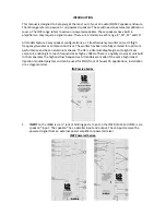
Input and output sockets, electronically balanced. The in XLR socket allows
connection of a low level signal source such as a microphone. The out XLR is parallel and
can be used as an output to link to another speaker into the jack line in (2) (Jack only on
IMP8)
2.
LINE.
Input is a ¼” jack for line level or instruments. This is the input used to connect from a
mixer
etc
3.
LINE/MIC.
These are signal lights from either the line in or mic in inputs
4.
GAIN.
Regulates pre-amplification of the signal coming from the input "IN", ensuring
perfect operation of the channel circuits.
5.
HIGH/MID/LOW.
3-band equalization to modify the required tone. These controls are
electronically post-gain and if boosted can clip the channel. This is indicated by the AACS
(clip light) indicator (see 9).If this occurs adjust the gain control anticlockwise. When the
potentiometers are set to "0" (indicated by a ‘notch’ in the dial) the tone is set to ‘flat’.
Clockwise will boost, anticlockwise will cut.
6.
TONE (IMP8 ONLY).
This is to adjust the tone. Clockwise from the 12 0 clock position will
add more treble whilst anti clockwise will add more bass.
7.
VOL.
Volume controls the signal level. Optimum performance is achieved with this set at
around 4 or 5 (level with ‘0’ on the tone controls)
8.
GND/LIFT.
2-position selector for separating the signal source ground and the amplifier
ground circuits. ON: the signal ground is electrically disconnected from the amplifier ground
circuit (the chassis). If hum is heard in the speakers, the ON position breaks the ground
loop. This is often the cause of the interference. OFF: the ground of the input signals is
electrically connected to the amplifier ground circuit (the chassis). USE GROUND LIFT ONLY
WITH BALANCED SIGNALS.
9.
CLIP (Automatic amplitude clip system)
when the audio signal reaches the dangerous
threshold for the transducers, this circuit will automatically cut in reducing the amount of
signal in order to protect the speaker.
10. PWR .
An LED light will indicate when the power is switched on or off.
11. AC power socket.
Is used to connect the unit to a power supply via enclosed power.
Caution: ensure the source voltage matches the voltage of product before turning on the
unit.
12. FUSE HOLDER.
The fuse holder is for containing the fuse, which is a safety device that
protects the AC supplies circuit of the unit. Caution: if the fuse blows, it should be replaced
with the same type and specification, if the fuse continues to blow, please refer servicing to
qualified
personnel.
13. VOLTAGE SELECTION SWITCH.
This switch provides two voltage selections: 115V or 230V,
please select the proper voltage depending on the voltage used.230v is used in the UK.
Содержание PA IM/IMP
Страница 1: ...IM RANGE OF PASSIVE AND ACTIVE SPEAKERS OWNERS MANUAL AND INSTRUCTION GUIDE ...
Страница 3: ......
Страница 8: ...E OE ...


