background image

Periodically tighten all nuts, bolts and screws and check that all fasteners are properly 
installed to ensure that the Z-Spray is in safe operating condition. 
 

Never

 perform maintenance on the Z-Spray while parking brake is 

disengaged


**Refueling your Z-Spray** 
 

Use only approved gasoline container. 
 
Never remove the gas cap or add fuel with the engine running. 
 
Extinguish all cigarettes, cigars, pipes, and other sources of ignition. 
 
Never fuel the machine indoors. 
 
Allow the engine to cool before refueling. 
 
If fuel is spilled on clothing, change clothing immediately 
 
If fuel is spilled, do not attempt to start the engine. Contain, remove and verify that all 
fuel has been removed before starting the machine. 
 
Remove Fuel Tank Cap 
 
Place a funnel in the Fuel Tank receptacle 
 
Slowly pour the fuel from the container into the receptacle. Don not pour to fast causing a 
spill (funnel will allow only so much fuel to drain into Fuel Tank) 
 
Replace Fuel Tank Cap and screw on tight. 


2.5


Storage Safety Rules 

**use fuel stabilizer if machine will sit for more than 30 days** 


Never

 store the Z-Spray in any area accessible by children. 


Never

 store the Z-Spray with fuel in the tank inside a building where fumes could reach 

an open flame or spark. 


Allow the Z-Spray engine to cool before storing in an enclosed area. 


Lubricate all moving parts of the Z-Spray to prevent rust during storage. 


Remove all accumulated debris from the Z-Spray and attachments before storing. 


SECTION 3     MAINTENANCE (Maintenance Chart in the back of manual) 


3.1


Engine Maintenance (Vanguard 16HP or 18HP) 


**USE COMPRESSED AIR (NOT WATER) WHEN CLEANING ENGINE** 


Use only original equipment replacement parts. Other parts may not perform as 
well, may damage unit, and may result in injury  


Page 4 


Содержание Z-Spray

Страница 1: ...OWNERS MANUAL Z Spray 60 Gallon Z Max 30 Gallon Intermediate Junior ...

Страница 2: ......

Страница 3: ...orage Safety Rules 4 SECTION 3 MAINTENANCE PAGE 3 1 Engine Maintenance 4 5 3 2 Hydraulic System Maintenance 5 3 3 Traction System Maintenance 6 3 4 Spray System Maintenance 6 7 3 5 Spreader System Maintenance 7 3 6 Attachment Maintenance Auxiliary Tanks Isolated Tank and or Foam Marker 7 8 Maintenance Chart 32 SECTION 4 Z SPRAY OPERATIONS PAGE 4 1 Overview 8 9 4 2 Operation 9 10 SECTION 5 SPRAY SP...

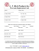
Страница 4: ...aler Name Dealer Address Dealer City State Dealer Phone Dealer Salesman Date of Purchase L T Rich Products warrants its line of equipment to be free from defects in material and factory workmanship for a period of 12 months Any exceptions to this will be explicitly stated in an individual warrant agreement in the operator s manual of that piece of equipment Not having this registration card in our...

Страница 5: ... of equipment to be free of defects in material and factory workmanship for a period of 12 months of purchase Any exception to this will be explicitly stated in an individual warranty agreement in the operator s manual of that stated piece of equipment This statement does not limit engine warranties in which the engine manufactures carry extended time periods beyond the 12 months Replacement parts...

Страница 6: ...ricants and fluids Damages to engine drive systems caused by a lack of or improper lubricants and or fluids Damages to engine drive system caused by improper operations and or maintenance SECTION 2 SAFETY INFORMATION 2 1 About This Manual The purpose of this manual is to assist you in properly and safely operating and maintaining the Z Spray Read and understand this entire manual before attempting...

Страница 7: ... Safety Rules Never operate the Z Spray without all covers shields and safety devices installed and secured Never permit any person other than the operator to ride or board the Z Spray at any time NEVER ALLOW RIDERS Use extreme care and maintain minimum ground speed when transporting on a hillside or over rough ground and when operating close to ditches fences or water The owner user can prevent a...

Страница 8: ...lowly pour the fuel from the container into the receptacle Don not pour to fast causing a spill funnel will allow only so much fuel to drain into Fuel Tank Replace Fuel Tank Cap and screw on tight 2 5 Storage Safety Rules use fuel stabilizer if machine will sit for more than 30 days Never store the Z Spray in any area accessible by children Never store the Z Spray with fuel in the tank inside a bu...

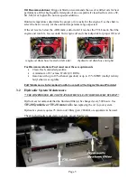
Страница 9: ...oil drain hose located on left side hydraulic oil drain hose on right Fuel Recommendations Fuel must meet these requirements Clean fresh unleaded gasoline A minimum of 87 octane 87 AKI 91 RON Gasoline with up to 10 ethanol gasohol or up to 15 MTBE methyl tertiary butyl ether is acceptable Full Maintenance Information Can Be Located In The Engine Manual Provided 3 2 Hydraulic System Maintenance USE...

Страница 10: ...tandard with 2 15 gallon tanks Additional tanks can be mounted upon request to either increase units liquid capacity or allow a unit to have a separate system for different liquid products that can disperse a host of liquid and or wettable powder To get maximum life and performance out of the spray system it is recommended that the tank s nozzles and hoses be flushed of all products after each use...

Страница 11: ...f different uses Like the spray system these attachments will need maintenance from time to time Auxiliary Tank part 80906 60 80930 AUX or 80905 60 This attachment is a separate tank that uses the pump provided on the existing unit Since it is cycled through the same system as the standard tank s this tank should be treated the same when going through a maintenance routine Flush all products out o...

Страница 12: ...The spray system has the ability to spray in 3 sections of the boom The wing booms left and right each have their own nozzles creating a 24 liquid path on either side The middle boom is equipped with 3 nozzles covering a 72 liquid path The 3 valves can be operated individually left right or middle or simultaneously together to create a 10 pattern Total spray pattern options consist of a 2 path eit...

Страница 13: ...es and streaks Determine a dial setting on the low side If setting is too low cover the area more than one time A higher setting can be used when a proven dial setting is established Travel at a constant speed for consistent results Remember Published dial settings are approximate only Open the hopper door after the spreader is turned on at operating speed 4 2 Operations Upon turning the key on to...

Страница 14: ...tay in the up position and cable would be extended out all the way When wanting to close off the left side and use the deflector shield push in the cable and the shield will drop down blocking off granular product on the left side The Locking Caster System allows the operator to lock the front caster wheels in the forward position to create more side hill stability The Locking Caster System is app...

Страница 15: ...urns on the spray system pump as well as the spot spray foot switch on the left side of the foot pan Once the pump is turned on the throttle valve is turned clockwise to increase pressure and or counter clockwise to release pressure and create agitation if the pump is on The pressure can be read on the gauge decreasing pressure from gauge will increase agitation in the tank Opening the chrome valv...

Страница 16: ... 000 sq ft We would recommend using 1 3 median value of 1 1 to 1 5 Since you are using a 1 3 gallon tip you need to multiply by 3 and then multiply that number of gallons you need to put in your tank 1 3 median value of 1 1 to 1 5 X 3 1 3 gallon tips X gallons needed If you were filling a 30 gallon tank your equation would look like this 1 3 X 3 X 30 117 ounces in 30 gallons of water 5 3 Spreader ...

Страница 17: ...n boom to boom To spray and spread at the same time Set the spread pattern to twice the width of the spray For example the 60 Gallon Z Max model has a spray width of 10 feet Set the spreader width to 20 feet and spread back to the tire tracks The spray pattern will match boom to boom This feathers material at the outer edges eliminating sharp edge to spread lines which cause stripes and streaks De...

Страница 18: ... for Junior not pictured 1 80310 Rim Seal 2 HHCSC5 3410 Front Wheel Bolt 1 NNC 34 Front Wheel Nut 1 FW SAE 34 Front Wheel Washer 1 Caster Parts Part Description Qty 80013 RS Suspension Caster Yoke Right 2015 to current 1 80013 LS Suspension Caster Yoke Left 2015 to current 1 80013 L Locking Caster Yoke Left 2009 to 2014 1 80013 R Locking Caster Yoke Right 2009 to 2014 1 80306 Dust Cap Steel 1 8030...

Страница 19: ... 1 80459 REVBB Tandem Pumps TL TBBA FBBB 6XHL 1 80402 15L Wheel Motor Large left 1 80402 15R Wheel Motor Large right 1 80413 3L250R Alternator Belt optional 1 ZSPRAY 60 ALT 60 AMP Alternator optional and not pictured 1 ZB200123 Alternator Bracket optional and not pictured 1 Foot Plate Parts Part Description Qty 80204 FOOT SWITCH ASSY Spot Spray Switch assembly 1 HFSSC 38112 Bolt 2 HFNCS 38S Nut 2 ...

Страница 20: ...Spot Spray Gun Part Qty Description 60040 1 ea Spot Spray Gun 60041 1 ea Spot Spray Tip 60029 1 ea MPT X 3 8 Barb Page 16 ...

Страница 21: ...120 lb 220 lb Hopper Parts Page 17 ...

Страница 22: ...Page 18 ...

Страница 23: ...Z Max Intermediate Junior Manifold Assembly Page 19 ...

Страница 24: ...Z Max Intermediate Junior Liquid Valve Assembly Page 20 ...

Страница 25: ...Intermediate Junior Boom Assembly Page 21 ...

Страница 26: ...Z Max Boom Assembly Page 22 ...

Страница 27: ...OLT FRONT CASTER WHEEL ASSY 2 ea 80021 ZMAX INT REAR WHEEL ASSEMBLY 20X10 5X8 2 ea 80020 JUNIOR REAR WHEEL ASSEMBLY 20X8X8 JUNIOR 2 ea 70014 220LB HOPPER CABLE 1 ea 70014 A 120LB HOPPER CABLE JUNIOR 1 ea 80352 A WHEEL HUB 2008 Z MAX n501053BP 2 ea 60012 THROTTLE VALVE n23520 3 4 PP 1 ea 60013 1 2 CHROME VALVE n90FML12 4 ea 60058 3 4 X 1 2 MPT RED NIPPLE 2 ea 60018 3 4 MPT X 3 4 HB 90 n3EL34 3 ea 6...

Страница 28: ... W BUTT CONNECTORS 1 ea 80304 IDLER PULLEY BRACKET BUSHINGS nKAMAN EF 1620 12 2 ea 80522 60 60 Gallon Exhaust Muffler 1 ea 80440 HYDRAULIC SPREADER MOTOR nMTE 207 1 ea 80204 FOOT FOOT SPOT SPRAY SWITCH ASSY 2010FS 01 1 ea 60000 L AVI 110025 1 3 SPRAY TIP 5 ea 80412 ENGINE DRIVE PULLEY 650492zyl 1 ea 70009 LARGE HOPPER COVER 220 1 ea 70008 SMALL HOPPER COVER 120 JUNIOR 1 ea 83067 Compression Foot P...

Страница 29: ... 4 HOSE BARB 90 2 ea 80432 AUX PUMP FITTING 2 n6400 04 04 2 ea 80032 3 Ball Joint Assembly 1 ea IGJCFXJCFX060606 36 36 RETURN HOSE 3 8 1 ea 83063 1 4 28 SS Ball Joint 367 2 SSE250 2 ea 60019 3 4 MPT X 3 4 HOSE BARB n3A34 1 ea 80429 PROPORTIONAL VALVE FITTING n6400 04 06 1 ea 80031 2 Ball Joint Assembly 1 ea IGJCFXXX0606 30 Wrapped 30 3 8 60ZMAX RETURN HOSE 1 ea IGJCFXXX0808 4 1 2 RETURN HOSE ASSEM...

Страница 30: ... ea LTBC 21R BATTERY CABLE 21 RED 1 ea 80035 5 Ball Joint Assembly 2 ea JCF06 JCMRE08 JIC37 FEMALE X JIC MALE 3 8X1 2 1 ea 86044 HOPPER HYDRO HOSE 44 ALL SPRAYERS 1 ea 80419 WHEEL MOTOR FITTING 4 n6801 08 10 4 4 ea 86042 8 Hopper Low Pressure Hose 1 ea 80430 1 2 PROP VALVE FTG 1 2 6400 08 08 4 ea 80315 5 8 Flange Bearing Joystick 4 ea 60019 12 1 2 x 1 2 mpt xbarb straight 3A12 4 ea 80432 B AUX PUM...

Страница 31: ...ise when running This could be caused by a couple of things The most common is if there is air in the system This can be caused when changing out a hydro pump replacing a hydraulic hose or having a loose fitting on the intake lines If air is not present check for low levels in the system This happens when there is a leak in the hydraulic system somewhere or hydraulic fluids were just changed and d...

Страница 32: ...r and the hopper base Also a potential factor is if the hopper cable is not completely closing the hopper door When your hopper door cannot open there are typically 3 things to look at One is that your hopper cable may be frozen and locked up the ball joint end may have broken off or there may be product jammed between the hopper door and the base due to loose door guides Spray System Liquid is dr...

Страница 33: ... IN THE FOLLOWING SEQUENCE Temporarily disconnect stator wire harness from regulator rectifier 1 Insert RED test lead into VΩ receptacle in meter 2 Insert BLACK test lead into COM receptacle 3 Rotate selector to V AC VOLTS position CAUTION Attach meter test leads to the AC output terminals YELLOW wires in the connector BEFORE starting the engine If the stator is grounded defective and the meter te...

Страница 34: ...or Rectifier Test Tools Required DC Shunt 19359 The DC Shunt MUST be installed on the NEGATIVE terminal of the battery Figure 32 to avoid blowing the fuse in the meter when testing the output of the 20 amp system All connections must be clean and tight for correct readings 1 Connect stator wire harness to regulator rectifier 2 Install DC Shunt 19359 4 on NEGATIVE battery terminal 3 Insert RED test...

Страница 35: ...Wiring Harness Page 31 ...

Страница 36: ...Hopper Tub wire brush cleaning X Hopper Bottom Bushing change if needed X replace Impeller change if needed X Engine Oil check X Engine Oil Change 50 hrs Engine Air Filter Check change if needed X replace 100 hrs Engine Air Pre Filter Check change if needed X replace 100 hrs Engine Fuel Filter Check change if needed X replace Engine Spark Plugs 100 hrs Hydraulic Oil change 500 hrs Hydraulic Oil Fi...

Отзывы: