


12XT
12XT
12XT
12XT
COAXIAL ENCLOSURE
COAXIAL ENCLOSURE
COAXIAL ENCLOSURE
COAXIAL ENCLOSURE
user manual
user manual
user manual
user manual
VERSION 1.3
12XT_UM_ML_1-3
w w w . l - a c o u s t i c s . c o m
14
14
14
14 en
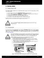
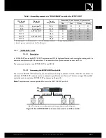
7.2.1.2
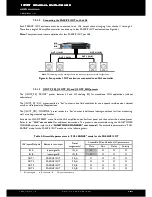
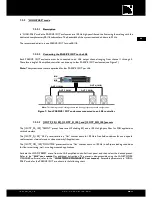
Connecting the PASSIVE 12XT to the LA4
Each PASSIVE 12XT enclosure must be connected to an LA4 output channel ranging from channel 1 through 4.
Therefore a single LA4 amplified controller can drive up to four PASSIVE 12XT enclosures (see Figure 6).
Note:
The system resources are optimized for four PASSIVE 12XT per LA4.
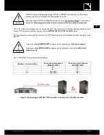
Figure 6: Four passive 12XT enclosures connected to an LA4 controller
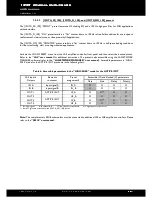
7.2.1.3
[12XTP_FR], [12XTP_FI], and [12XTP_MO] presets
The [12XTP_FR] ‘‘FRONT’’ preset features LF and HF shelving EQ for standalone FOH applications (without
subwoofers).
The [12XTP_FI] ‘‘FILL’’
preset results in a ‘‘flat’’ contour in free field conditions for use in speech reinforcement, classical
music, or close proximity fill applications.
The [12XTP_MO] ‘‘MONITOR’’ preset results in a ‘‘flat’’ contour in half-space loading conditions for floor monitoring,
wall, or ceiling-mounted applications.
Activate the LOAD PRESET menu from the LA4 amplified controller front panel and then select the desired preset.
Refer to the
‘‘LA4’’
user manual
for additional instructions. The preset is also accessible using the LA NETWORK
MANAGER software (refer to the
‘‘LA NETWORK MANAGER’’ user manual
). The accessible parameters in ‘‘FULL
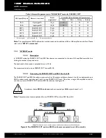
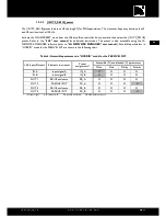
RANGE’’ mode for the PASSIVE 12XT are shown in the following chart:
Table 2: Accessible parameters in ‘‘FULL RANGE’’ mode for the PASSIVE 12XT
Accessible (O) and blocked (X) parameters
LA4 Inputs/Outputs
Elements to connect
Preset
assignments*
Mute
Gain
Delay
Polarity
IN A
Input signal A
IN_A
X
O
O
O
IN B
Input signal B
IN_B
X
O
O
O
OUT 1
PASSIVE 12XT
PA_A
O
O
O
O
OUT 2
PASSIVE 12XT
PA_A
O
O
O
O
OUT 3
PASSIVE 12XT
PA_B
O
O
O
O
OUT 4
PASSIVE 12XT
PA_B
O
O
O
O
* IN: input signal. A, B: channel A, B. PA: passive enclosure.
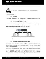
IN A
IN B
Note:
This drawing is only a cabling scheme and does not represent a valid configuration.
OUT 2 (IN A)
OUT 1 (IN A)
OUT 3 (IN B)
OUT 4 (IN B)
Содержание 12XT
Страница 2: ...w w w l a c o u s t i c s c o m ...
Страница 28: ...w w w l a c o u s t i c s c o m ...
Страница 54: ...w w w l a c o u s t i c s c o m ...
Страница 55: ...w w w l a c o u s t i c s c o m ...


