L
4x10mm
4x10mm
3x12mm
3x12mm
No.6, No.10
13
Part bags used.
17
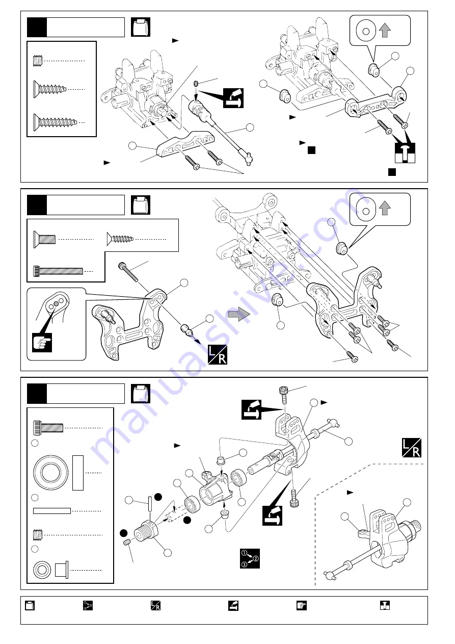
Front Suspension
2
2.6 x 17mm
Shaft
Apply threadlocker
(screw cement).
Assemble in the
specified order.
Assemble left and right
sides the same way.
4
4 x 10mm
Cap Screw
4
7
39
8 x 16mm
Ball Bearing
2
5 x 4mm
Set Screw
70
Knuckle Collar
4
Pay close attention here!
No.5, No.6, No.10
Tighten the set screw to
the flat spot.
15
Front Gearbox
240
59
4x20mm
5x4mm
1
5 x 4mm
Set Screw
4 x 15mm
TP F/H Screw
2
4 x 20mm
TP F/H Screw
2
Tentatively
tighten.
For now, no need to tighten
screws firmly. Tighten the
screws firmly in page 14 step .
4 x 10mm
F/H Screw
4
2
3 x 12mm
TP F/H Screw
61
63
63
4x15mm
No.5, No.6,
No.10
16
Front Shock Stay
2
3 x 20mm
Cap Screw
27
242
65
65
3x20mm
Holes for
mounting.
Top
L
H
Top
A
B
66
71
70
70
38
7
7
68
39
69
67
4x10mm
4x10mm
5x4mm
1
2
3
“L” marked.
“R” marked.
< >
< >
For left side.
For right side.
Use the "L" marked piece.
4x15mm
Use the "A" marked piece.
Use the " 22° " marked piece.
19
使用する袋詰。
フロントサスペンション
シャフト
ネジロック剤を塗る。
番号の順に組立てる。
左右同じように組立てる。
キャップビス
ベアリング
セットビス
ナックルカラー
注意して組立てる所。
フロントギヤボックス
TP
サラビス
セットビス
TP
サラビス
平らな面にセットビスを
固定する。
仮止め。
ここで仮止めし、
14
ページ
で組立て後本締する。
サラビス
TP
サラビス
フロントダンパーステー
上
キャップビス
取付穴
上
“L”
のマーク
“R”
のマーク
< >
< >
左側用
右側用
“L”
を使用。
“A”
を使用。
“ 22° ”
を使用。
19
Содержание INFERNO MP777 SPECIAL 2
Страница 1: ......
Страница 2: ......
Страница 3: ......
Страница 4: ......
Страница 5: ......
Страница 6: ......
Страница 7: ......
Страница 8: ......
Страница 9: ......
Страница 10: ......
Страница 11: ......
Страница 12: ......
Страница 14: ......
Страница 15: ......
Страница 16: ......
Страница 17: ......
Страница 18: ......
Страница 19: ......
Страница 20: ......
Страница 21: ......
Страница 22: ......
Страница 23: ......
Страница 24: ......
Страница 25: ......
Страница 26: ......
Страница 27: ......
Страница 28: ......
Страница 29: ......
Страница 30: ......
Страница 31: ......
Страница 32: ......
Страница 33: ......
Страница 34: ......
Страница 35: ......


